
Balanced fan plenum for distributing particulate material

a technology of particulate material and fan plenum, which is applied in the field of agricultural equipment, can solve problems such as imbalances in the pressure of the static air, and achieve the effects of minimizing imbalance between the lines, maximizing fan efficiency, and maximizing manufacturability

Active Publication Date: 2022-06-07
CNH IND CANADA
View PDF23 Cites 1 Cited by
  • Summary
  • Abstract
  • Description
  • Claims
  • Application Information

AI Technical Summary

Benefits of technology

The solution achieves balanced airflow distribution, reducing power consumption and improving performance by maintaining airflow separation and balance across all lines, even during sectional control, and compensating for imbalanced fan effects.

Problems solved by technology

However, such sectional control can result in static pressures imbalances across the lines of the distribution system which can be problematic, contributing to an inefficiency which requires operating the fan at a higher power consumption level to ensure that all lines receive a minimum airflow.

Method used


Image

  • Balanced fan plenum for distributing particulate material
  • Balanced fan plenum for distributing particulate material
  • Balanced fan plenum for distributing particulate material

Examples


Embodiment Construction

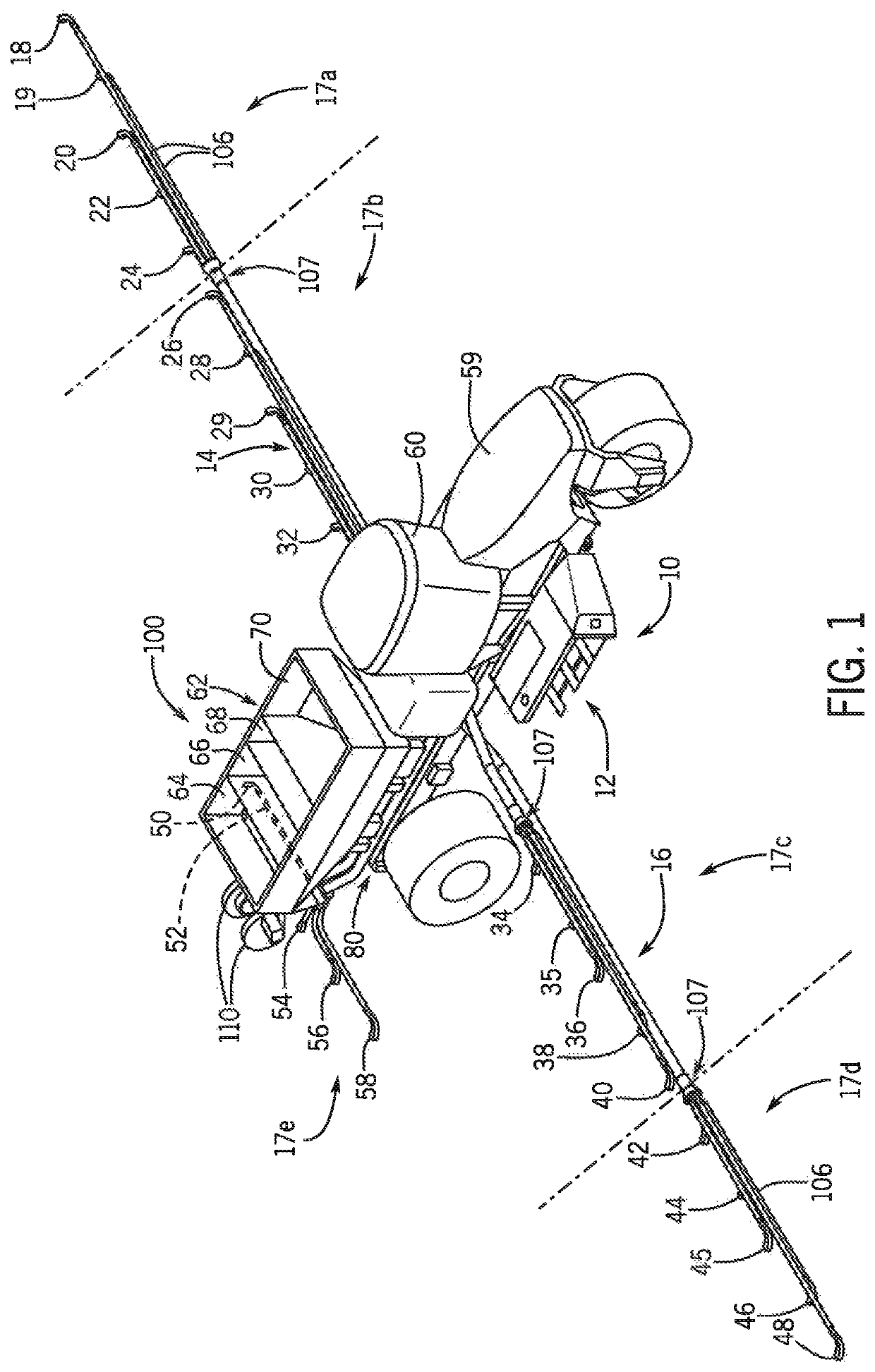
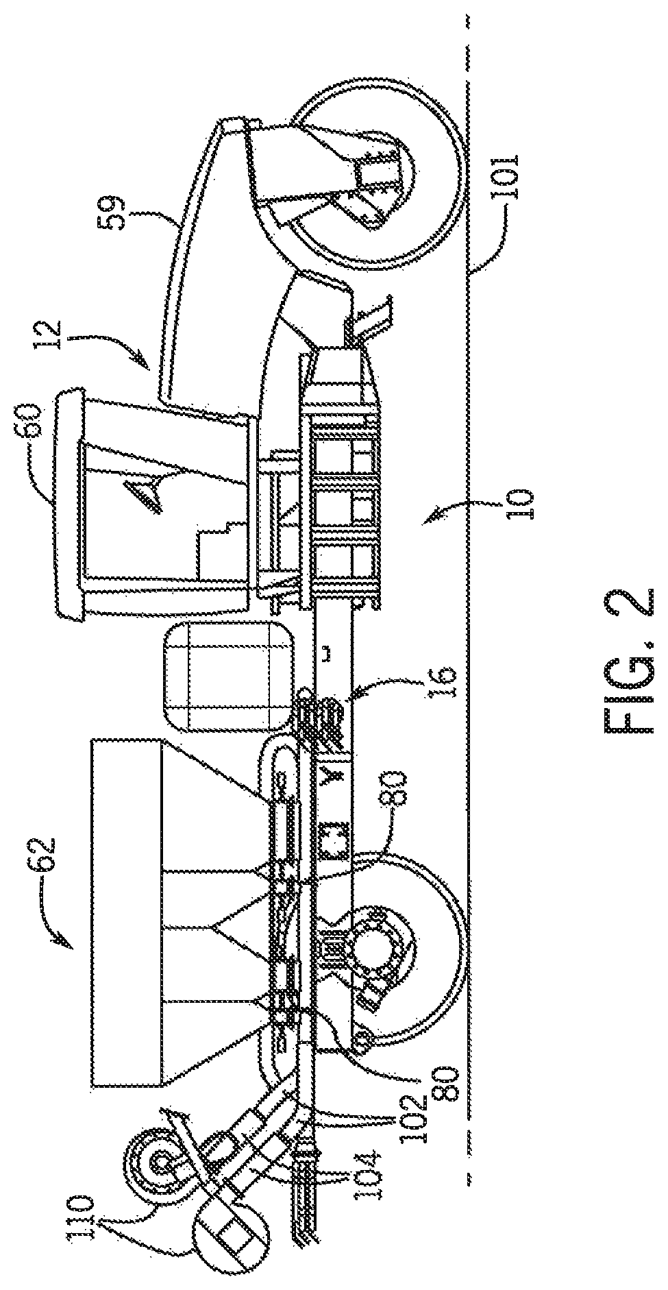
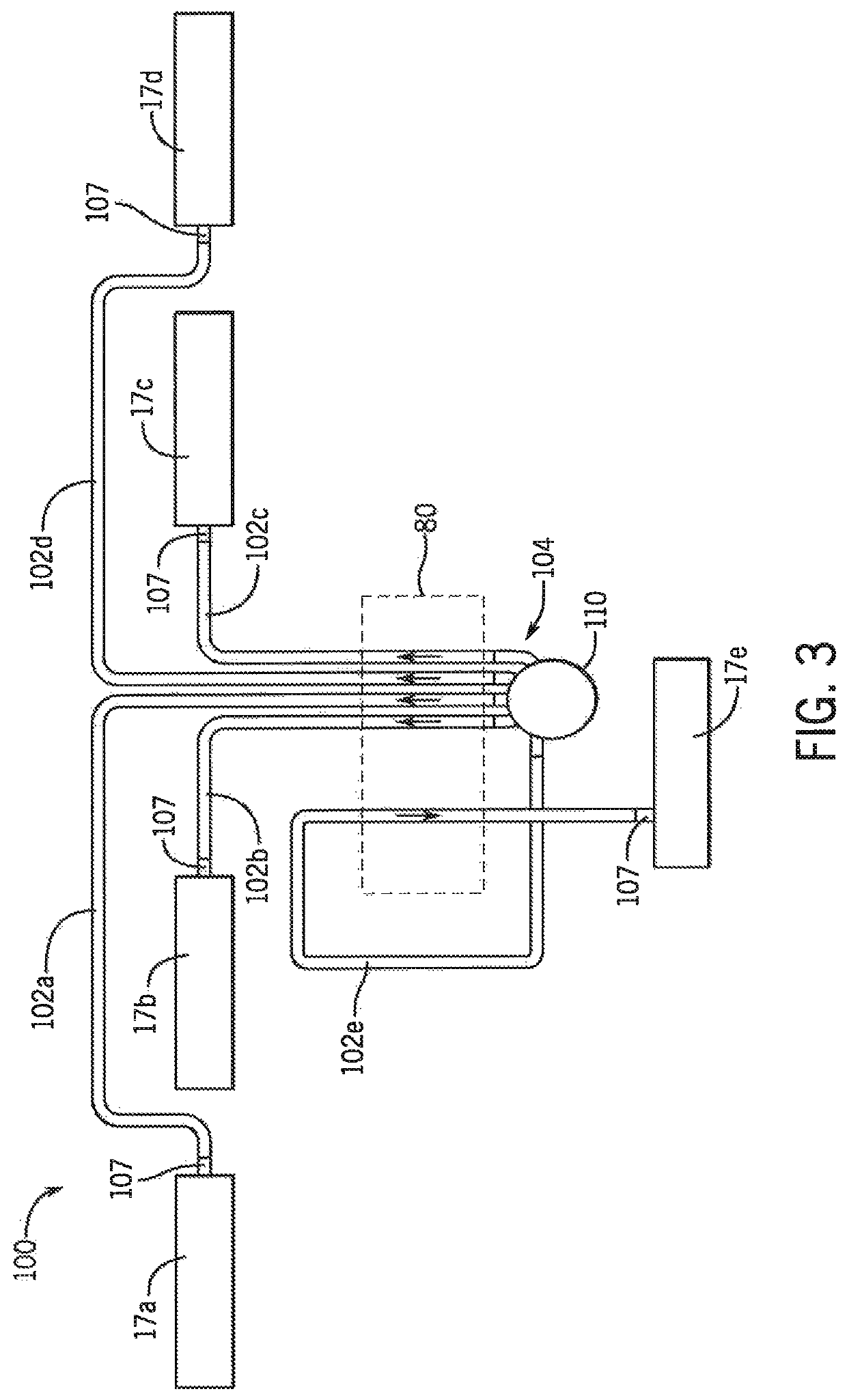
[0020]Referring now to the drawings, and more particularly to FIGS. 1 and 2, there is shown an agricultural application implement 10, which could be a dry pneumatic granular applicator. As is known in the art, implement 10 generally includes a large wheeled transport unit 12 such as truck or tractor, and laterally extending particle delivery booms 14 and 16, which may be pivoted to a stowed position close to the implement for storage or transport. Each boom 14, 16 extends laterally from the implement 10 in opposite directions. Each boom 14, 16 includes a plurality of boom sections 17, such as left outer and left inner boom sections 17a, 17b of boom 14, and right inner and right outer boom sections 17c, 17d of boom 16. Each boom section 17 is defined by a large diameter supply line 102 for supplying the boom section with granular or particulate material, such as seed, fertilizer, herbicide, insecticide and the like. Each boom section 17 includes a plurality of boom tubes or conduits ...


PUM


Abstract

The present invention provides a plenum configured to evenly separate and distribute airflow generated by a fan into distribution lines of an agricultural machine. The plenum can utilize angled vanes symmetrically or asymmetrically arranged to form plenum chambers to provide a balanced airflow which contributes to maximizing fan efficiency, including power consumption and performance (airflow and static pressure). Accordingly, the plenum can be configured to separate the airflow and minimize imbalance between the lines during sectional control. The plenum height can be maintained for increased manufacturability and to prevent additional expansion. The plenum length can be configured within allowable space constraints of the machine yet allow airflow to develop upon separation into the lines. Vanes throughout the span of the plenum initially divide the airflow from the fan and maintain separation until the outlets.

Description

FIELD OF THE INVENTION[0001]The present invention pertains to agricultural equipment and, more specifically, to a system for distributing particulate material from an applicator in which a plenum coupled to a fan divides an airflow into multiple airflow components, each airflow component being directed through a plenum chamber, with each plenum chamber being separated from an adjacent plenum chamber by a plenum vane configured at an angle relative to the adjacent plenum chamber with the plenum chambers being configured in a symmetrical arrangement.BACKGROUND OF THE INVENTION[0002]Agricultural product delivery systems are known to utilize various mechanisms, including mechanical and pneumatic systems to move granular or particulate material or product, such as fertilizer, seed, insecticide or herbicide, from a product supply chamber, through a series of elongated tubes that extend from a product supply chamber to a product applicator, and placing the product on, or in a growing mediu...

Claims


Application Information

Patent Timeline
Patent Type & Authority Patents(United States)
IPC IPC(8): A01C7/08A01C15/04B65G53/50A01M9/00B65G53/42
CPCA01C15/04A01C7/084A01C7/082A01M9/003B65G53/42B65G53/50
Inventor DENIS, JOELFERRE, SAMUEL
Owner CNH IND CANADA
Learn More