Method for producing high-pressure sensors

a high-pressure sensor and sensor technology, applied in the direction of fluid pressure measurement, manufacturing tools, instruments, etc., can solve the problems of uncomplicated alignment of two components, and achieve the effect of convenient implementation and easy configuration

Active Publication Date: 2013-12-03
ROBERT BOSCH GMBH
View PDF13 Cites 0 Cited by
  • Summary
  • Abstract
  • Description
  • Claims
  • Application Information

AI Technical Summary

Benefits of technology

[0008]The present invention provides a construction concept for high-pressure sensors that enables simple and economical production of reliable high-pressure sensors even for pressure ranges above 2200 bar.
[0011]In a particularly advantageous variant of the method according to the present invention, circuit elements for signal acquisition are applied onto the base element of the sensor element in the diaphragm region before the base element of the sensor element is mounted on the base element of the connector piece. With this method variant, the circuit elements can also be implemented using technologies that, because of the dimensions of the connector piece, can no longer readily be utilized after assembly, for example by the application of semiconductor processes. The circuit elements can thus easily be implemented in a thin-layer structure having at least one deflection-sensitive, i.e. for example piezoresistive or piezoelectric, layer.
[0012]In the context of the method according to the present invention, sensor elements and connector pieces made of steel or a steel alloy are preferably used. The two components of the pressure sensor construction according to the present invention can likewise be implemented in the form of blanks made of a sintered material. With these materials, the full-area connection between the two base elements is advantageously produced by welding. The pressure conduit in the connector piece and the diaphragm of the sensor element can then easily be configured using a suitable technology, for example electropolishing, drilling, or milling. Depending on the materials of the base element and the desired shape of the pressure connection, different methods can also be combined for this purpose.

Problems solved by technology

Alignment of the two components is also very uncomplicated in this case.

Method used


Image

  • Method for producing high-pressure sensors
  • Method for producing high-pressure sensors

Examples


Embodiment Construction

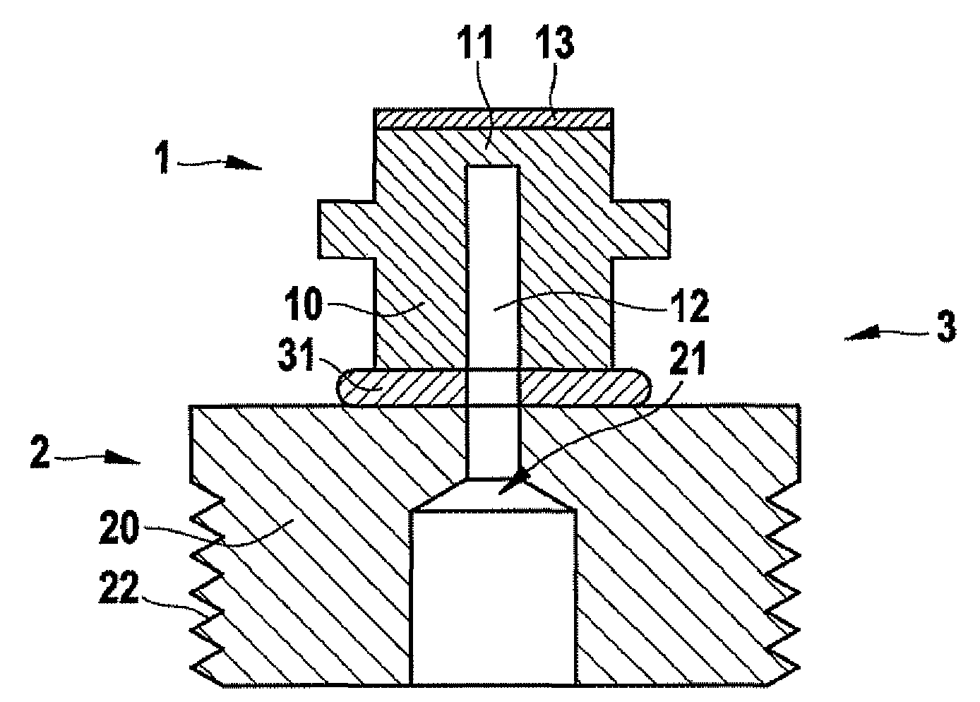
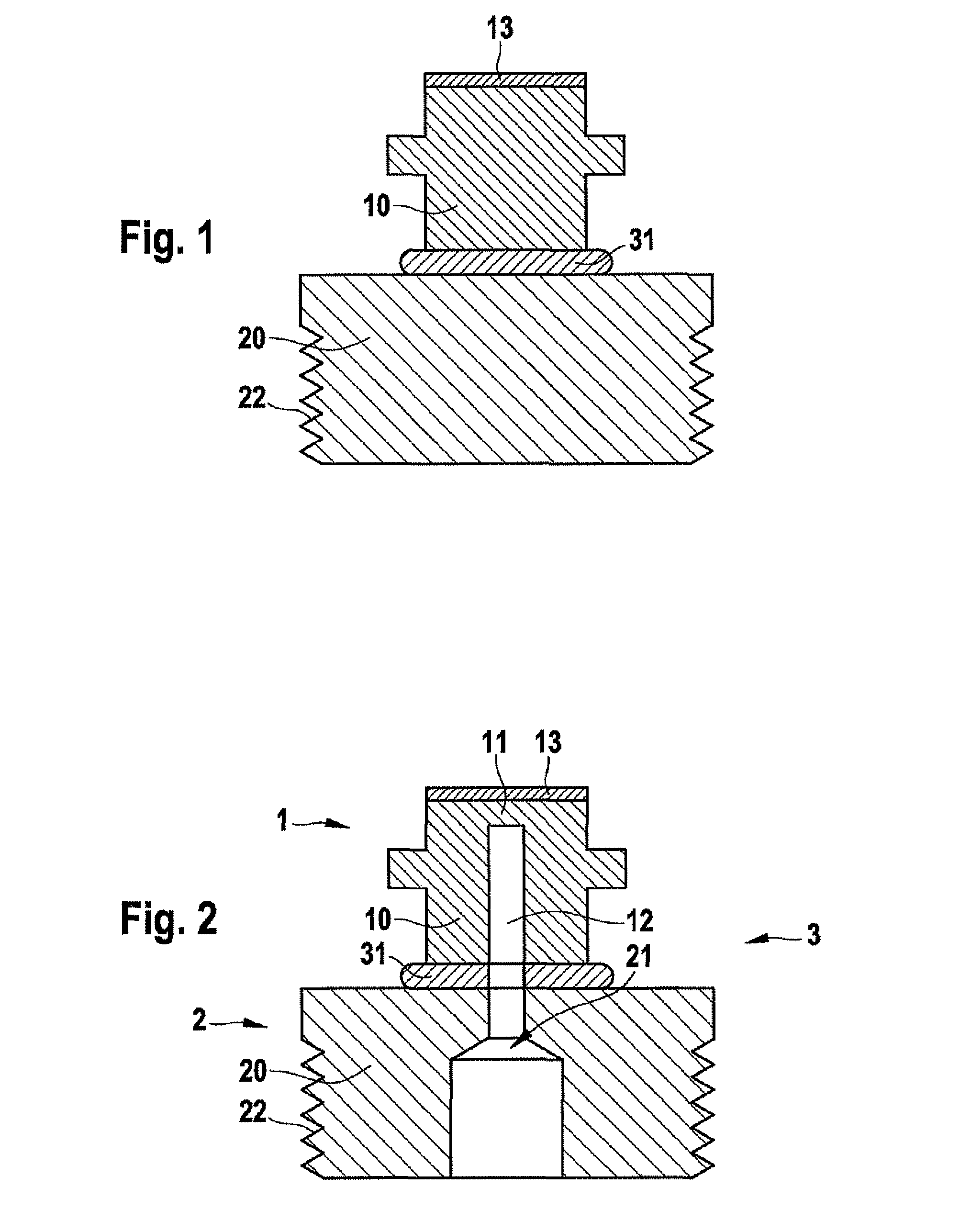
[0015]FIGS. 1 and 2 illustrate the method according to the present invention for producing a high-pressure sensor 3 (as depicted in FIG. 2) having a sensor element 1 for pressure sensing and having a connector piece 2 for coupling sensor element 1 to a system to be measured. According to the present invention, base element 10 of sensor element 1 is mounted on base element 20 of connector piece 2 before a diaphragm 11 is configured in sensor element 1 and a suitable pressure connector, in the form of a blind opening 12 in sensor element 1 and a pressure conduit 21 adjoining it, is configured in connector piece 2. This structuring of the two base elements 10 and 20 is accomplished only after a full-area connection 31 has been produced between the mounting surfaces of the two base elements 10 and 20.

[0016]FIG. 1 shows the construction after assembly of the two base elements 10 and 20. Base element 10 of sensor element 1 is a relatively thin metallic support on which a thin-layer constr...


PUM

PropertyMeasurementUnit
pressureaaaaaaaaaa
pressuresaaaaaaaaaa
pressureaaaaaaaaaa

Abstract

A construction concept for high-pressure sensors is provided, which enables simple and economical production of reliable high-pressure sensors even for pressure ranges above 2200 bar. A high-pressure sensor of this kind encompasses a sensor element for pressure sensing and a connector piece for coupling the sensor element to a system to be measured. A diaphragm is embodied in the base element of the sensor element, and a pressure conduit is embodied in the base element of the connector piece. The sensor element is mounted on the connector piece so that the pressure to be measured is able to act upon the diaphragm via the pressure conduit. Firstly the base element of the sensor element is mounted on the base element of the connector piece, a full-area connection being generated between the mounting surfaces of the two base elements. Only thereafter is the pressure conduit configured in the connector piece, and the diaphragm of the sensor element exposed.

Description

FIELD OF THE INVENTION[0001]The present invention relates to a method for producing high-pressure sensors having a sensor element for pressure sensing, and having a connector piece for coupling the sensor element to a system to be measured. A diaphragm is embodied in the base element of the sensor element, and a pressure conduit is embodied in the base element of the connector piece. The sensor element is mounted on the connector piece in such a way that the pressure to be measured is able to act upon the diaphragm via the pressure conduit.BACKGROUND INFORMATION[0002]A variety of concepts for constructing high-pressure sensors having a sensor element and a connector piece are known from practical use.[0003]These two components are usually fabricated independently of one another from a metallic base element. In the case of the sensor element, the base element is equipped with a blind opening in order to expose a diaphragm in the oppositely located surface of the base element. Circuit...

Claims


Application Information

Patent Timeline
Patent Type & Authority Patents(United States)
IPC IPC(8): H01S4/00
CPCG01L19/0007Y10T29/49002Y10T29/49826Y10T29/49004
Inventor HENNING, FRANKFREY, WILHELM
Owner ROBERT BOSCH GMBH
Why Eureka
Try Eureka