Carton with reinforced hand holes

a hand-hole and carton technology, applied in the field of cartons, can solve the problems of unreasonable user carrying a full heavy-weight carton, injury to the end user, and inability to carry a full-size carton, and achieve the effects of preventing injury, stable lifting, and strong structur

Active Publication Date: 2013-12-03
PAIGE ELECTRIC CO LP
View PDF17 Cites 29 Cited by
  • Summary
  • Abstract
  • Description
  • Claims
  • Application Information

AI Technical Summary

Benefits of technology

[0006]Another embodiment of this disclosure is similar to that just described with the addition of a third primary hand hole formed in the alternate lifting panel. This affords a user the option of placing the two adapters in any of three positions so the user can select where he or she wants the reinforced hand holes to be located. This is desirable because some users prefer to have two hand holes on the top of the carton and others prefer to have one hand hole on top and one hand hole on the bottom of the carton. With the selectably locatable adapters, all users get to have their preference met. Alternately, a fourth hand hole could be included and the two adapters could be placed in any of the four positions, creating an even more stable lift which further prevents the possibility of injury.
[0008]Still another aspect of the present disclosure concerns the adapter structure. It has a mating wall engageable with a panel of a carton. A back wall is connected to the mating wall. A bottom wall is connected to the back wall. The mating and bottom walls have side edges which define a maximum width of the adapter. At least one gusset plate extends from one of the mating and bottom walls toward the other, the gusset plate being spaced from the side edges of the wall that defines the maximum width of the adapter. The inwardly spaced gusset plates provide a stronger structure that can withstand the weight of the coil.

Problems solved by technology

Previous non-reel cartons typically were limited to carrying 15 to 20 pounds of wire.
One of the challenges of a heavy weight carton is providing a way to carry it.
It is not reasonable to expect a user to carry a full heavy weight carton weighing 100 pounds in one hand.
The hand holes have to be strong enough to prevent them from tearing out under load, which could possibly cause injury to the end user.

Method used


Image

  • Carton with reinforced hand holes
  • Carton with reinforced hand holes
  • Carton with reinforced hand holes

Examples


Embodiment Construction

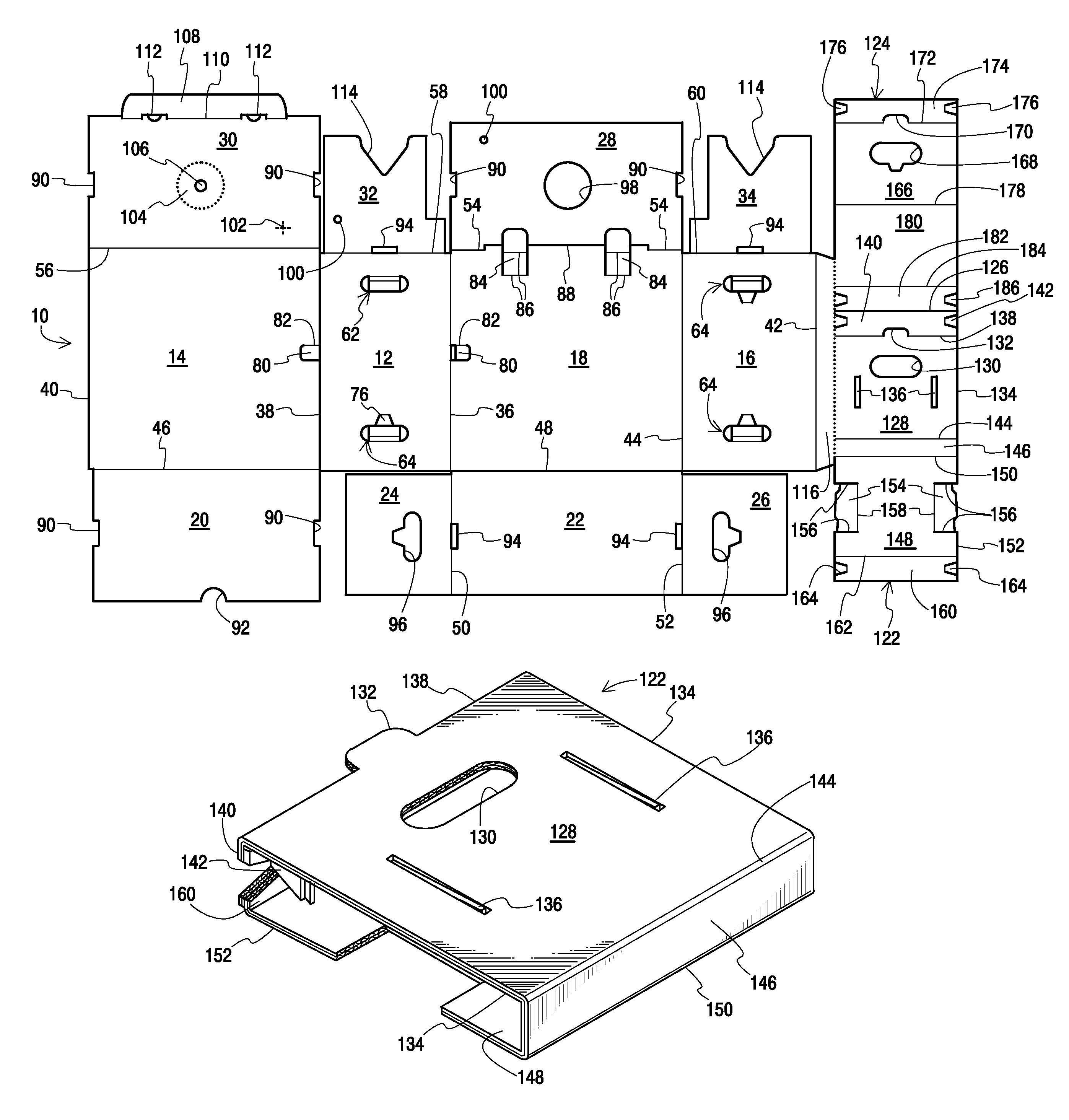
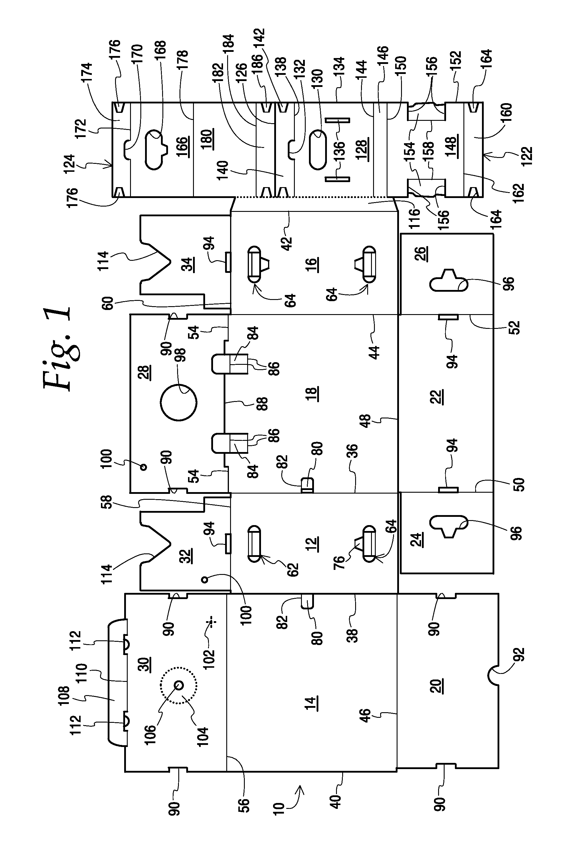
[0038]FIG. 1 illustrates a carton blank 10 for the carton of the present invention. The carton is preferably made of heavy weight stock material, such as double wall corrugated cardboard. Other materials could be used, such as corrugated plastic. Preferably the corrugations run vertically as seen in FIG. 1. The blank shows the carton at one stage of its manufacture wherein it is completely flat. This stage is prior to subsequent stages which include: forming a joint between two of the panels; removing the adapter blanks; setting up the carton and adapters; and assembly of the carton including installation of the adapters. In FIG. 1 the interior lines of lighter weight indicate fold lines. Heavier lines indicate portions that are fully cut through the stock. Dotted lines indicate perforations. Also, portions of the carton will be designated herein as top, bottom, left, right, front and rear. It will be understood that these designations are for reference purposes only and the carton ...


PUM


Abstract

A carton has a lifting panel, at least one alternate lifting panel, side, front and rear panels that collectively define an interior space for receiving a heavy weight of non-reel coil of filamentary material or coil products such as wire. The panels may include three hand holes, two of which are reinforced by two adapters insertable into the interior space. One form of adapter is assembled from a blank of foldable material and has top, front, bottom and back walls reinforced by gusset plates which are located remotely from the side edges of the top and bottom walls. The maximum width of the adapter top and bottom walls is less than the distance between opposed side panels of the carton. First and second retention members are formed in the panels and extend into the interior space of the carton where they are engageable with the adapters to support them adjacent a hand hole.

Description

BACKGROUND OF THE INVENTION[0001]The advantages of non-reel cartons for packaging filamentary materials such as wire, cable and rope are set forth in U.S. patent application Ser. No. 11 / 675,755, filed Feb. 16, 2007, the disclosure of which is incorporated herein by reference. The present disclosure concerns cartons for holding filamentary materials that are capable of receiving a heavy weight of filamentary material such as wire. By way of example, the carton of the present disclosure is capable of carrying over 100 pounds of wire. Previous non-reel cartons typically were limited to carrying 15 to 20 pounds of wire. The additional capacity of the present carton enables the non-reel carton to replace the larger sizes of wooden reels that were used to package wire. This affords significant cost savings as well as environmental benefits since the cardboard carton is fully recyclable, unlike the standard wooden reel it replaces.[0002]One of the challenges of a heavy weight carton is pro...

Claims


Application Information

Patent Timeline
Patent Type & Authority Patents(United States)
IPC IPC(8): B65D5/468
CPCB65D5/443B65D5/445B65D5/4608
Inventor BABCOCK, KENNETH R.
Owner PAIGE ELECTRIC CO LP
Why Eureka
Try Eureka