

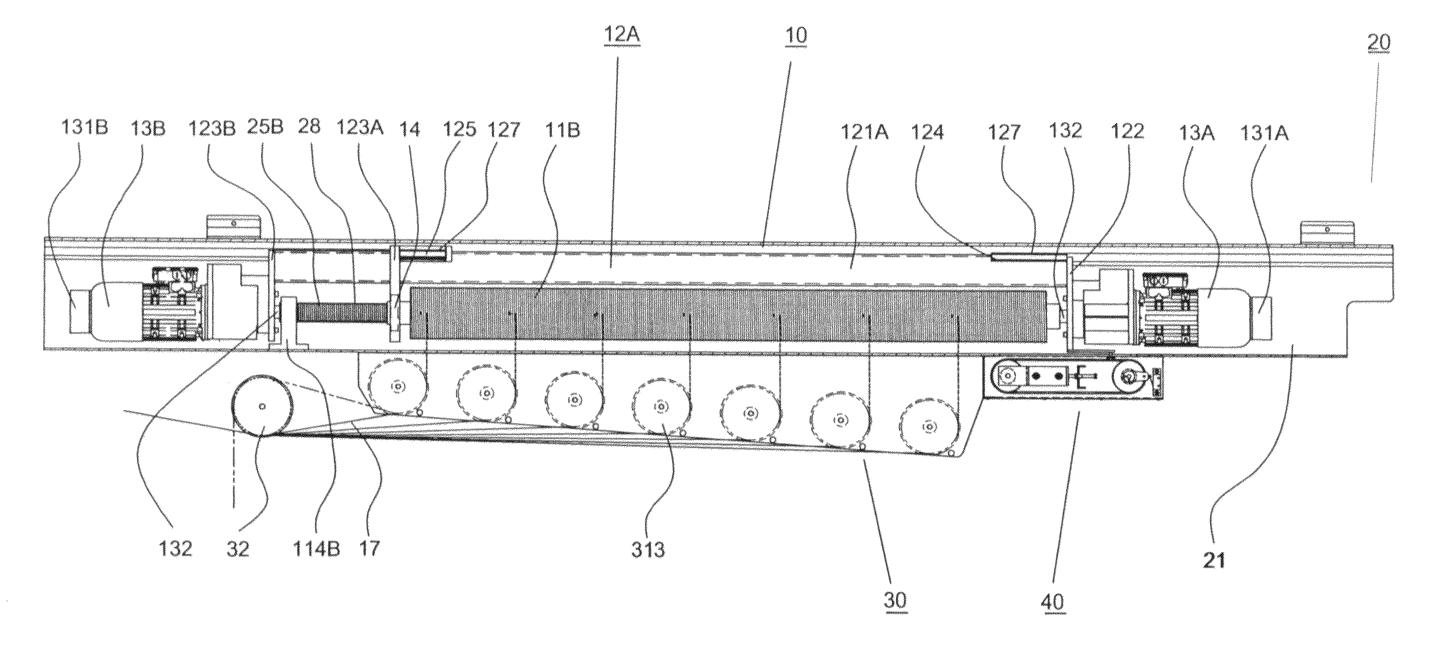
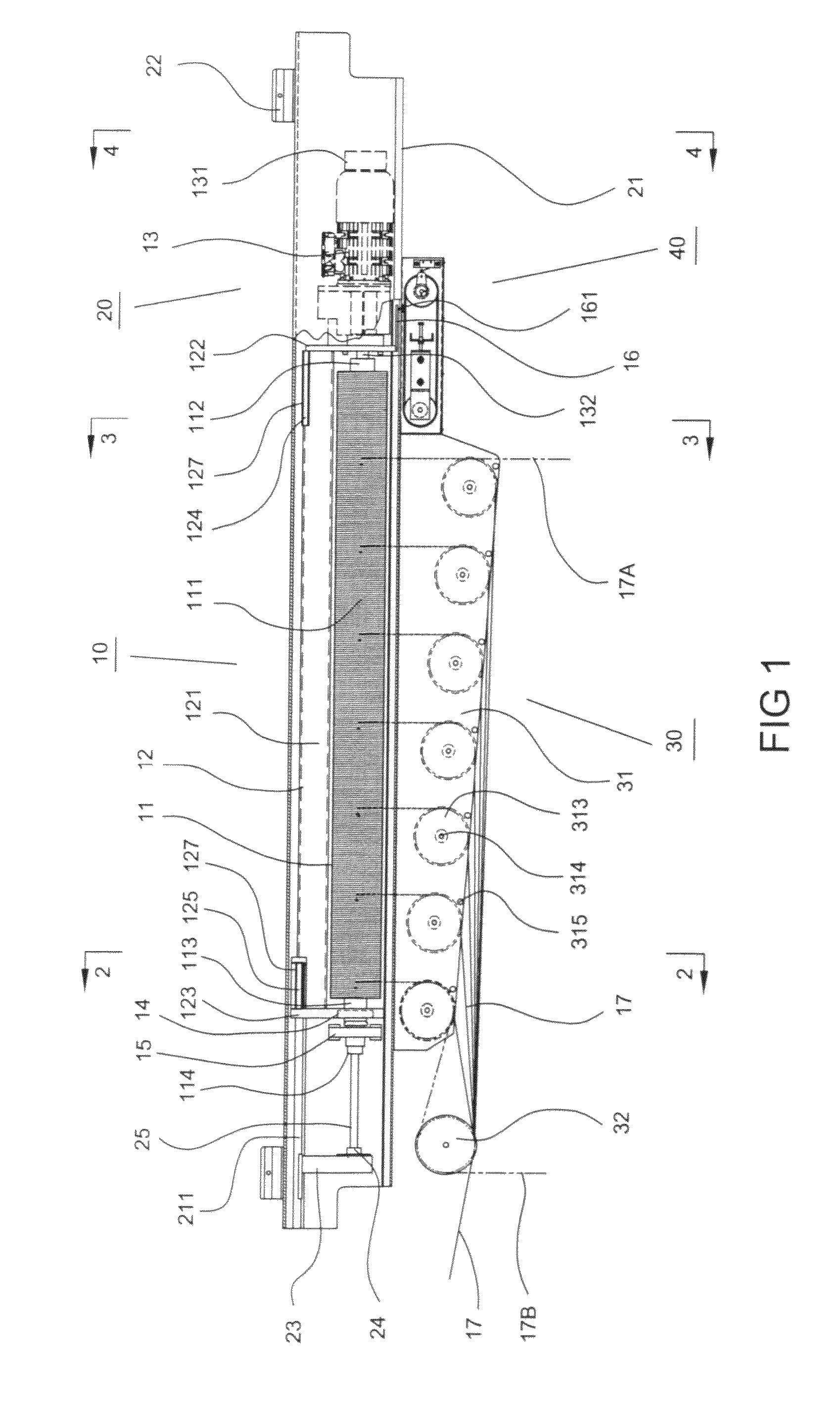
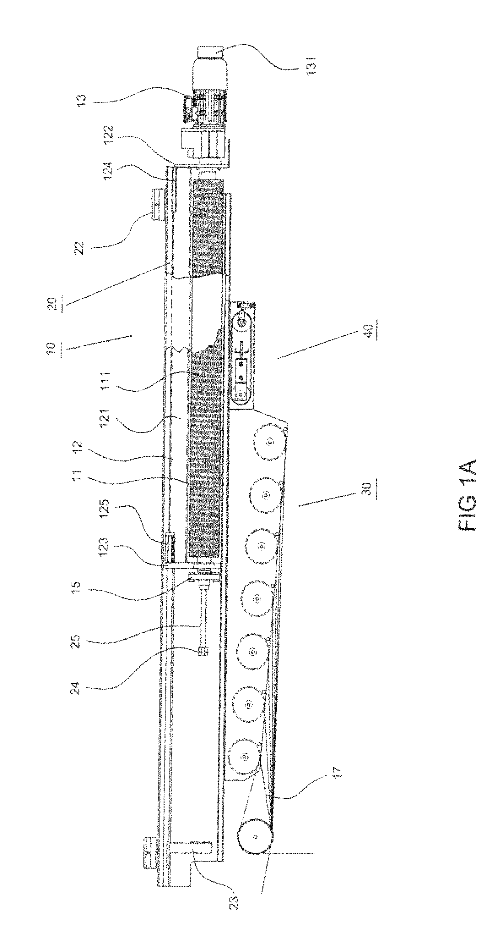
Winch for raising and lowering theatre scenery
a technology for theatre scenery and winch, which is applied in the direction of theatre/circus, stage arrangements, hoisting equipment, etc., can solve the problems of flying set running away, many accidents, time-consuming and dangerous loading and unloading of counterweights for balancing loads, etc., to reduce friction, improve operational life, and reduce wear and tear
- Summary
- Abstract
- Description
- Claims
- Application Information
AI Technical Summary
Benefits of technology
Problems solved by technology
Method used
Image

Examples
Embodiment Construction
[0044]As used in this application, a “fly set” typically is the combination of a batten, loft blocks (sheaves) and one or more support lines, for example, a wire cable or rope, attached to the batten and engaging a loft block. Typically, the number of loft blocks equals the number of support lines. A “batten” is the structural member typically supporting a scenic element. Typically the batten is a steel or aluminum pipe, though other strip-type structural members can be substituted. When the scenery to be raised and lowered is, for example, a screen or backdrop extending laterally across the stage, the supporting batten typically has a length exceeding the width of the proscenium, i.e., the stage opening visible to the audience, and the batten would typically use 4-7 support lines spaced evenly across its top. As used herein, the terms “laterally” and “width” refer to the horizontal dimension or direction of the proscenium and the term “vertically” refers to the vertical dimension o...
PUM
 Abstract
Description
Claims
Application Information