Image processing apparatus and image processing method

a technology of image processing and image processing, applied in the field of image processing apparatus and image processing method, can solve the problems of not providing information to the representation image, viewer or editor of the image cannot view not only “what is shown", and achieve the effect of good symbol visibility

Inactive Publication Date: 2013-12-03
SONY CORP
View PDF7 Cites 0 Cited by
  • Summary
  • Abstract
  • Description
  • Claims
  • Application Information

AI Technical Summary

Benefits of technology

[0012]As described above, in the above-mentioned embodiment, a symbol indicative of a full-screen movement is drawn on the rim of the scene representative image made up of a union image. Therefore, this novel configuration allows the user to understand not only the entire image in each scene but also the movement of each screen in one scene. In addition, a symbol indicative of a full-screen movement is drawn in accordance with the display size of a representative image in an output device. Therefore, if the display size of a representative image in an output device is relatively small, the visibility of each symbol is ensured.
[0017]In the above-mentioned embodiment, the symbol drawing block draws, as the symbol, a symbol shaped in a line extending in a direction orthogonal to a direction of the full-screen movement and sets a length of the normal symbol to be drawn with the cumulative number of the predetermined screen being not larger than N to a length corresponding to a magnitude of the full-screen movement of the predetermined screen, for example. The symbol drawing block sets a length h of the normal symbol to be drawn with the cumulative number of the predetermined screen being at least 1 and not larger than N to H*Mv / Mvmax, where H is the length of a direction orthogonal to the direction of the full-screen movement in a display area of the rim in the output device, Mvmax is a maximum movement among the full-screen movements, and My is a full-screen movement of each screen, for example. In this case, the length of a normal symbol to be drawn in each screen corresponds to the full-screen movement of that screen, thereby increasing the volume of the information indicated by this drawn normal symbol.
[0018]In the above-mentioned embodiment, the symbol drawing block determines a proximity of the symbols to be drawn to each other and, in accordance with a result of this determination, changes a drawing manner of the normal symbol to be drawn with the cumulative number of the predetermined screen being at least 1 and not larger than N, for example. In this case, the symbol drawing block computes the distance d between symbols closest to each other on the display area by relation W*Vmin / (S+T) where S is a length of one screen in a direction of the full-screen movement, T is a total value of the full-screen movements, Vmin is a minimum movement when no accumulation is found in the full-screen movement, and W is a length of in the direction of the full-screen movement of a display area of the representative image in the output device, thereby determining the proximity of between the symbols on the basis of the distance d obtained as above, for example. Thus, changing the manner of drawing a symbol to be drawn with the cumulative number of the predetermined screen being not larger than N in accordance with a result of the symbol proximity determination allows the user to easily understand a full-screen movement from a drawn symbol if the display size of a representative image in an output device is relatively small.
[0021]In the above-mentioned case, because darkly drawn normal symbols are thinned out, if the display size of a representative image in an output device is relatively small, the drawn normal symbols are not crowded too much to make it difficult for the user to understand full-screen movements, for example. Also, in this case, the length of a normal symbol drawn in each screen corresponds to the full-screen movement of that screen, thereby increasing the volume of the information indicated by this normal symbol.
[0023]In the above-mentioned case, for the symbols indicative of a full-screen movement, reduced symbols (an acceleration symbol, a uniform velocity symbol, and a deceleration symbol) are drawn. If the display size of a representative image in an output device is relatively small, the number of symbols to be drawn can be decreased, thereby preventing the drawn symbols from crowded too much to make it difficult for the user to understand full-screen movements. In addition, this novel configuration allows the user to easily understand the acceleration period, uniform velocity period, and deceleration period of each full-screen movement.
[0027]Further, according to the embodiments of the invention, a symbol indicative of a full-screen movement is drawn in accordance with the display size in an output device of a representative image, so that, even if the display size of a representative image in the output device is relatively small, a good symbol visibility is provided.

Problems solved by technology

However, this representative image does not provide information such as how fast the subject is panned, for example.
This presents a problem that a viewer or an editor of an image cannot overview not only “what is shown” but also “what is shown in what expression” in a certain scene.

Method used


Image

  • Image processing apparatus and image processing method
  • Image processing apparatus and image processing method
  • Image processing apparatus and image processing method

Examples


first embodiment

1. First embodiment

Exemplary Configuration of Image Processing Apparatus

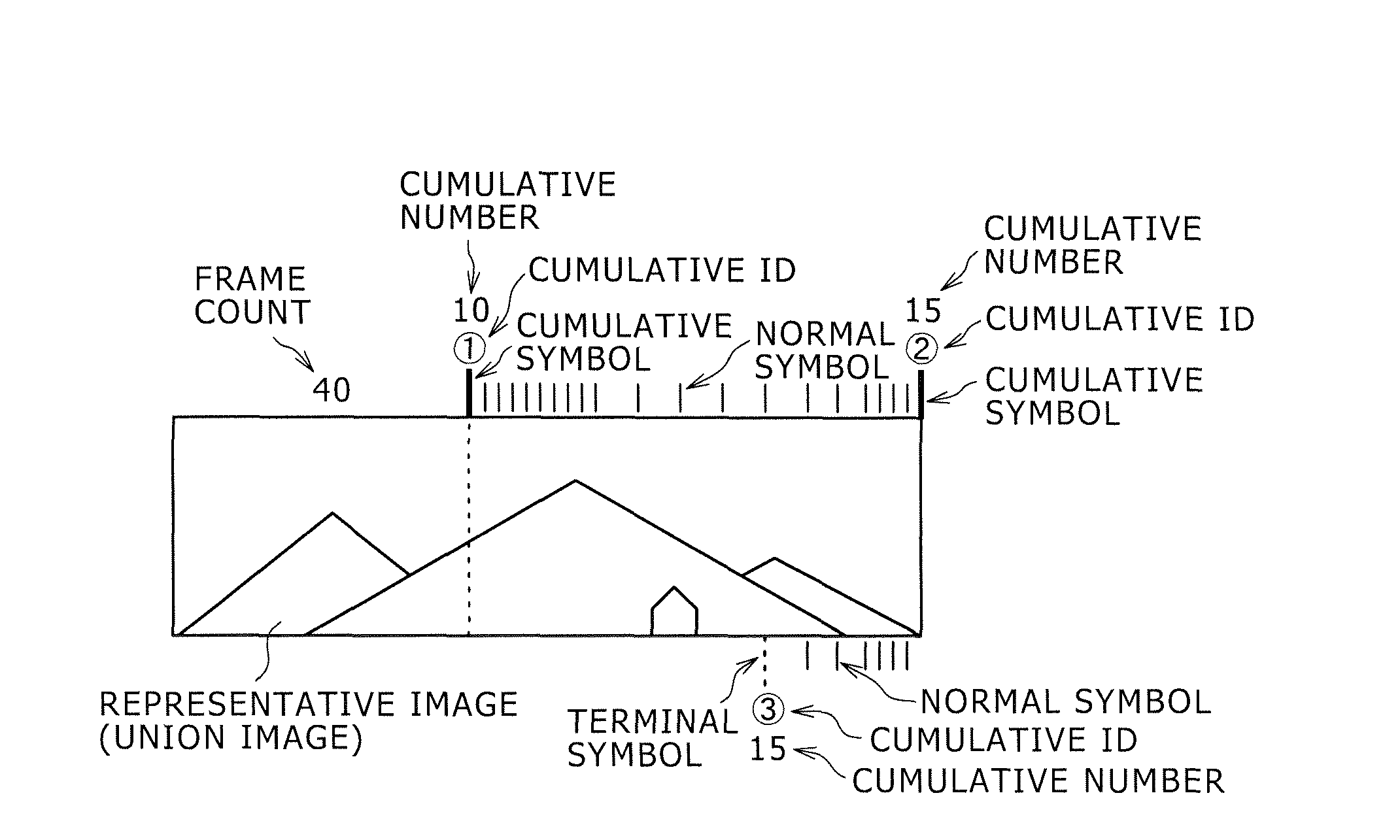
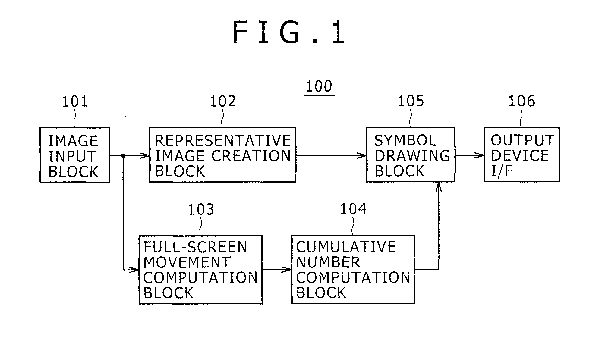
[0070]Now, referring to FIG. 1, there is shown an exemplary configuration of an image processing apparatus 100 that is practiced as the first embodiment of the present invention. This image processing apparatus 100 has an image input block 101, a representative image creation block 102, a full-screen movement computation block 103, a cumulative number computation block 104, a symbol drawing block 105, and an output device interface (I / F) 106.

[0071]The image input block 101 inputs an image signal to be processed into the image processing apparatus 100. This image signal to be processed, obtained by taking a subject with an imaging device (a camera, for example), is directly supplied from the imaging device or read from a predetermined recording media to be supplied. In addition, this image input block 101 detects a scene change point by processing the inputted image signal, divides the inputted signal by scene, a...

second embodiment

2. Second Embodiment

Exemplary Configuration of Image Processing Apparatus

[0147]Referring to FIG. 16, there is shown an exemplary configuration of an image processing apparatus 100B practiced as the second embodiment of the invention. The image processing apparatus 100B has an image input block 101, a representative image creation block 102, a full-screen movement computation block 103, a cumulative number computation block 104, a symbol drawing block 105B, an output device interface I / F 106, and a thin-out number computation block 108. With reference to FIG. 16, components similar to those previously described in FIG. 1 are denoted by the same reference numerals and detail description thereof is skipped.

[0148]For example, the distance d between the symbols that are closest to each other in the display area is computed to determine the proximity between the symbols on the basis of the obtained distance d. The distance d is computed by equation (1) below by use of the length S in the ...

third embodiment

3. Third Embodiment

Exemplary Configuration of Image Processing Apparatus

[0175]Referring to FIG. 25, there is shown an exemplary configuration of an image processing apparatus 100A practiced as the third embodiment of the invention. The image processing apparatus 100A has an image input block 101, a representative image creation block 102, a full-screen movement computation block 103, a cumulative number computation block 104, a symbol drawing block 105A, an output device interface (I / F) 106, and a uniform velocity number computation block 107. Referring to FIG. 25, components similar to those previously described with reference to FIG. 1 are denoted by the same reference numerals and detailed description thereof is appropriately skipped.

[0176]The image input block 101 inputs an image signal to be processed into the image processing apparatus 100A. This image signal to be processed is obtained by taking a subject with an imaging device (a camera) for example and supplied directly fro...


PUM


Abstract

Disclosed herein is an image processing apparatus including: a representative image creation block configured to create, as a representative image, a union image with images of screens making up a predetermined scene linked with each other; and a symbol drawing block configured, on the basis of a full-screen movement of each screen in the predetermined scene, to draw a symbol indicative of the full-screen movement on a rim of the representative image created by the representative image creation block, wherein the symbol drawing block draws the symbol indicative of the full-screen movement in accordance with a display size of the representative image to be displayed on an output device.

Description

BACKGROUND OF THE INVENTION[0001]1. Field of the Invention[0002]The present invention relates to an image processing apparatus and an image processing method and, more particularly, to an image processing apparatus and an image processing method that are configured to create an image of union as a representative image for each scene.[0003]2. Description of the Related Art[0004]In the past, a subject that cannot be entirely held in one screen of an imaging device (a camera) is taken as divided in two or more frames by use of pan or tilt technique. FIG. 36 shows an example in which a subject extending in the horizontal direction is taken with an imaging device (camera) by use of a pan technique.[0005]Also, it has been practiced to process taken or created image signals to select a predetermined screen (a first screen for example) for each scene, providing the image of the selected screen as a representative image. In this case, a viewer or an editor, for example, cannot grasp the enti...

Claims


Application Information

Patent Timeline
Patent Type & Authority Patents(United States)
IPC IPC(8): G06T7/20
CPCH04N5/23238H04N5/23293H04N5/91H04N9/8205H04N5/783H04N9/8227H04N23/698H04N23/635
Inventor TAKAGI, YOSHINORI
Owner SONY CORP
Why Eureka
Try Eureka