Sheet shutter

a technology of shutters and sheets, applied in the direction of shutters/movable grilles, door/window protective devices, constructions, etc., can solve the problems of reducing mobility and losing elasticity, and achieve the effects of reducing the weight of the support post, increasing the strength of the support post and the outer rail, and reducing the thickness

Active Publication Date: 2013-12-10
KOMATSU ELECTRIC SANGYO
View PDF15 Cites 20 Cited by
  • Summary
  • Abstract
  • Description
  • Claims
  • Application Information

AI Technical Summary

Benefits of technology

[0018]With the above-described configuration, in the case where, due to an impact caused when the sheet receives a strong wind or is brought into contact with a person or an object, strong force acts to move both left and right ends of the sheet and the inner rails on both sides of the sheet inward in the left and right direction, the elastic sheet section made of the urging member is deformed by being curved or bent in the gap space, so that the resulting elastic force acts toward the side to reduce the strong force directed inward in the left and right direction, and thereby the impact is reduced. However, in this case, the elastic sheet section deformed by being curved or bent is brought into contact with only a part of the groove side surface because of the surface shape of the elastic sheet section. Thereby, the impact to the sheet and the wear of the urging member can be reduced without impeding the smooth movement of the inner rail in the left and right direction. Further, the gap space is partitioned by the elastic sheet section into the front and rear portions, and hence washing water, rain water, dust, and the like, can be efficiently prevented from entering the side of the groove side surface of the rail groove.
[0019]In addition, in the case where the elastic sheet section is made of a member without water permeability, even when the sheet shutter is used in a food factory, or the like, in which spray washing with tap water is performed daily, it is possible to efficiently prevent that the washing water permeates through the urging member to enter a portion near the groove side surface of the gap space.
[0020]Further, when the rail base is integrally extended in the front and rear direction from the bottom surface side end portion of the rail groove of the inner rail toward the groove side surface, and when the opposite wall extended in the front and rear direction from the open end side of the rail groove of the outer rail so as to face the rail base is integrally provided, and when the elastic sheet section is inserted between the rail base and the opposite wall, the positional deviation of the elastic sheet section can be suppressed, so that the elastic sheet section can be stably installed between the rail base and the opposite wall.
[0023]Further, when the opening side contact section is formed so as to close the gap space on the open end side of the rail groove, it is possible to more effectively prevent water, dust, and the like, from entering the inside of the rail groove.
[0024]Note that, when the rail base side end portion of the elastic sheet section is formed integrally with the rail base, the elastic sheet section is prevented from being detached from the inner rail, so that the elastic force can be stably applied to the inner rail from the elastic sheet section.
[0026]Further, when the outer rail is formed integrally with the inner wall forming the left-and-right inner end of the support post, and with the intermediate wall formed at the left-and-right intermediate portion in the support post so that the inner wall and the intermediate wall are connected by the outer rail, the strength of the support post and the outer rail can be increased while their thickness is reduced, and the weight of the support post and the manufacturing cost can be reduced.

Problems solved by technology

Further, the above-described urging member is generally manufactured by processing a sponge made of rubber or a synthetic resin material into a block shape, and has a disadvantage that it wears due to the reciprocating movement, and that, because of its poor weather resistance, it is deteriorated at an early stage so as to lose the elasticity for stretching the sheet.
Further, there is a problem that, when the urging member becomes brittle, a small fragment broken off from the urging member enters the gap between the side wall and the rail base so as to reduce the mobility of the inner rail.

Method used


Image

  • Sheet shutter
  • Sheet shutter
  • Sheet shutter

Examples


Embodiment Construction

[0045]Embodiments according to the present invention will be described with reference to the drawings.

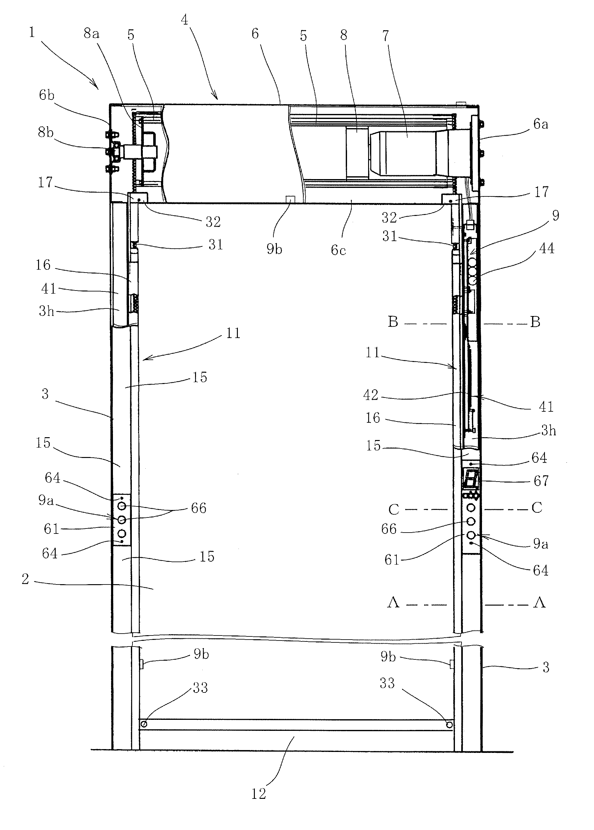
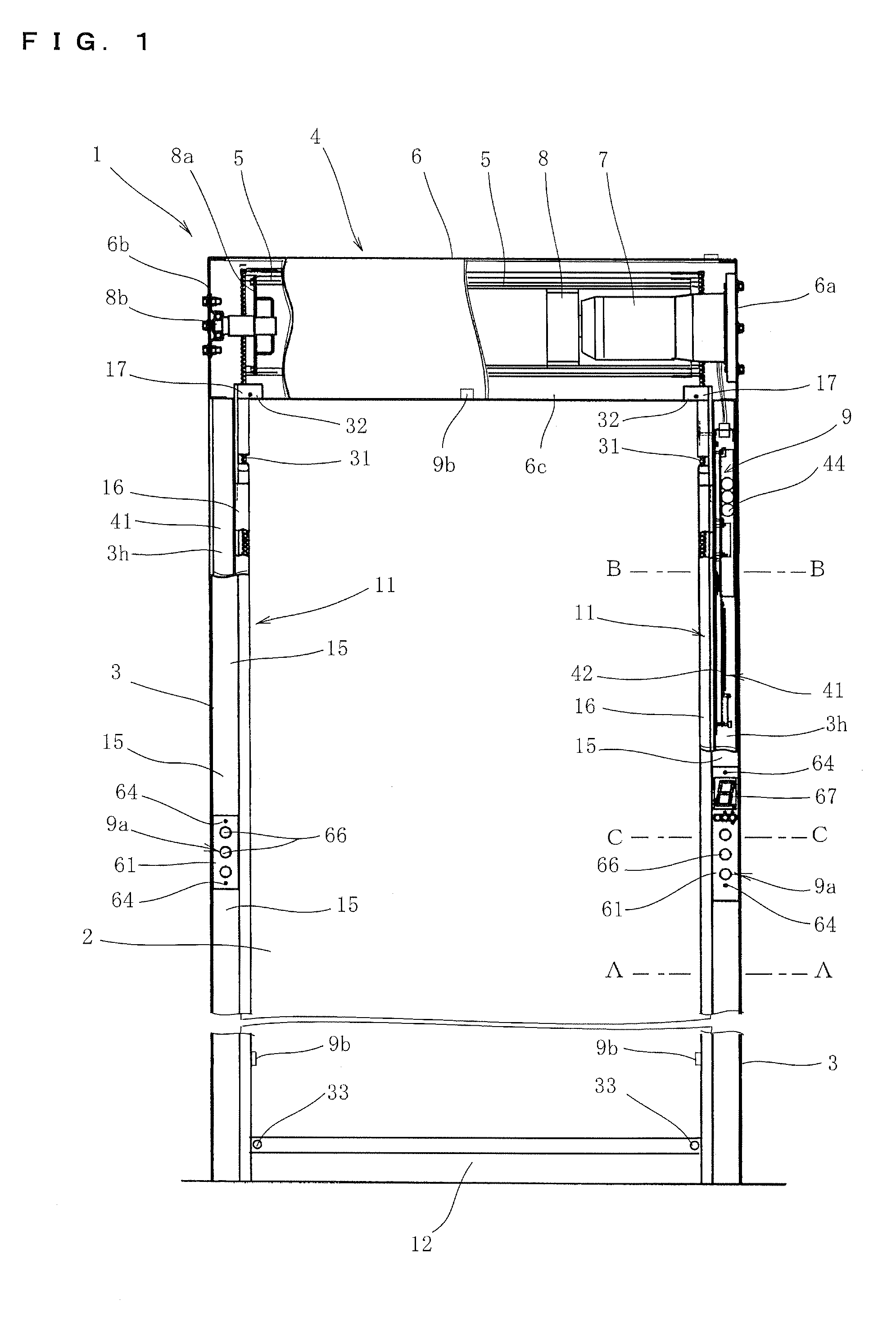
[0046]FIG. 1 is a front view showing the whole of a sheet shutter according to the present invention. Reference numeral 1 denotes a sheet shutter installed mainly in an entrance of a building, and is configured by a support post 3 (side frame) which is configured as a guide member for supporting each of left and right end portions of a sheet 2 for the shutter so as to guide the vertical up and down movement of the sheet 2, a cylindrical sheet case 4 which incorporates an opening and closing mechanism of the sheet 2, and the like. The support post 3 is attached and fixed along a post or a wall which is arranged at the entrance of the building. The sheet case 4 is installed laterally along an installation portion, such as the beam or the wall surface of the building, and is attached in the state of being mounted on the left and right support posts 3.

[0047]In the sheet shutter 1 shown ...


PUM


Abstract

To provide a sheet shutter in which an urging member for urging an unwound, sheet toward the left and right outer side is provided so that the sheet is made to smoothly slide in the left and right direction and the wear of the urging member is suppressed. The sheet shutter according to the present invention is configured such that a rail groove is provided in each of left and right support posts, such that an inner rail is accommodated and supported in the rail grooves, such that engagement guides for guiding the lifting and lowering of the sheet formed in the inner rails, and such that, when the urging member is provided in the rail groove, an elastic sheet section for partitioning the inside of the rail groove into front and rear portions is provided at the urging member.

Description

BACKGROUND OF THE INVENTION[0001]1. Field of the Invention[0002]The present invention relates to a sheet shutter which can be installed in an entrance and a partition portion of a building, such as a factory and a warehouse, and which can be installed in various apparatuses.[0003]2. Description of the Related Art[0004]Conventionally, a sheet shutter is widely known which is installed in an entrance and a partition portion of a building, such as a factory or a warehouse, and in which a sheet provided to be able to be wound and unwound around a sheet drum is lifted and lowered along support posts provided on both sides of the sheet. In such a sheet shutter, there is known a sheet shutter in which a vertically directed rail groove whose left and right inner side is opened is formed in an outer rail formed in each of left and right support posts, in which an inner rail is provided in the rail groove, and an engagement guide engaging with each of left and right end portions of a sheet in...

Claims


Application Information

Patent Timeline
Patent Type & Authority Patents(United States)
IPC IPC(8): E06B9/13
CPCE06B9/13E06B9/581E06B2009/585E06B9/08E06B9/11E06B9/56E06B9/68E05Y2600/456E05Y2800/43
Inventor KOMATSU, AKIOADACHI, HITOYUKIHORIE, YOSHIAKIFUJII, TAKESHI
Owner KOMATSU ELECTRIC SANGYO
Why Eureka
Try Eureka