System and method for scavenging ullage from center wing tanks in an airplane

a technology of center wing tanks and ullage, which is applied in the direction of machines/engines, transportation and packaging, and wellbore/well accessories, etc., can solve the problems of unreliable system and high power consumption of electrically powered air pumps in aircraft systems

Inactive Publication Date: 2013-12-10
SIMMONDS PRECISION PRODS
View PDF8 Cites 54 Cited by
  • Summary
  • Abstract
  • Description
  • Claims
  • Application Information

AI Technical Summary

Benefits of technology

[0007]The systems that utilize electrically powered air pumps have impractically high power consumption for an on-board aircraft system. In one embodiment, the subject technology provides air flow with little or no power consumption to overcome this disadvantage. Further, electrically powered air pumps may break down creating an unreliable system. The subject technology may be deployed with minimal moving parts and, thus, greatly improved reliability.
[0012]Typically, the fuel tank is a center wing tank of an airplane and airplane engine bleed air is used to power the air driven unit and pre-heat the main catalytic unit. A valve preferably operates to selectively provide the airplane engine bleed air to the main catalytic unit. In one embodiment, a secondary catalytic unit creates heated ullage for the main catalytic unit, wherein the secondary catalytic unit is relatively smaller than the main catalytic unit. If beneficial, an orifice can restrict ullage flow to the secondary catalytic unit.

Problems solved by technology

There are problems associated with prior art systems that address safety concerns associated with ullage in CWT of airplanes.
The systems that utilize electrically powered air pumps have impractically high power consumption for an on-board aircraft system.
Further, electrically powered air pumps may break down creating an unreliable system.

Method used


Image

  • System and method for scavenging ullage from center wing tanks in an airplane
  • System and method for scavenging ullage from center wing tanks in an airplane
  • System and method for scavenging ullage from center wing tanks in an airplane

Examples


second embodiment

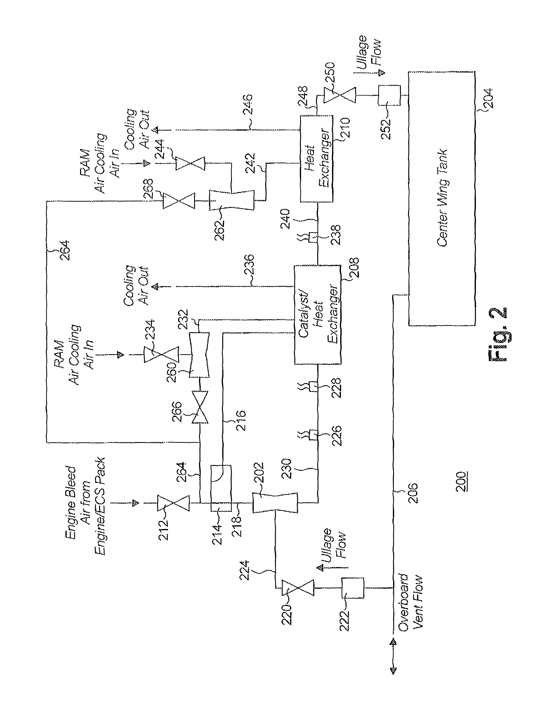
[0034]Referring now to FIG. 2, a schematic view of another system for scavenging and returning ullage to center wing tanks in an airplane is shown. As will be appreciated by those of ordinary skill in the pertinent art, the system 200 utilizes similar principles to the system 100 described above. Accordingly, like reference numerals preceded by the numeral “2” instead of the numeral “1”, are used to indicate like elements. The following description is directed primarily to the differences of the system 200 in comparison to the system 100, namely using engine bleed air through additional ejector venturis 260, 262 to provide additional catalytic cooling during ground operations.

[0035]Compared to prior art systems, the subject technology requires relatively less engine bleed air. Consequently, the remaining available bleed air can be advantageously used elsewhere in the system 200 for cooling the catalyst / heat exchanger 208 and second heat exchanger 210. A benefit of this method is tha...

third embodiment

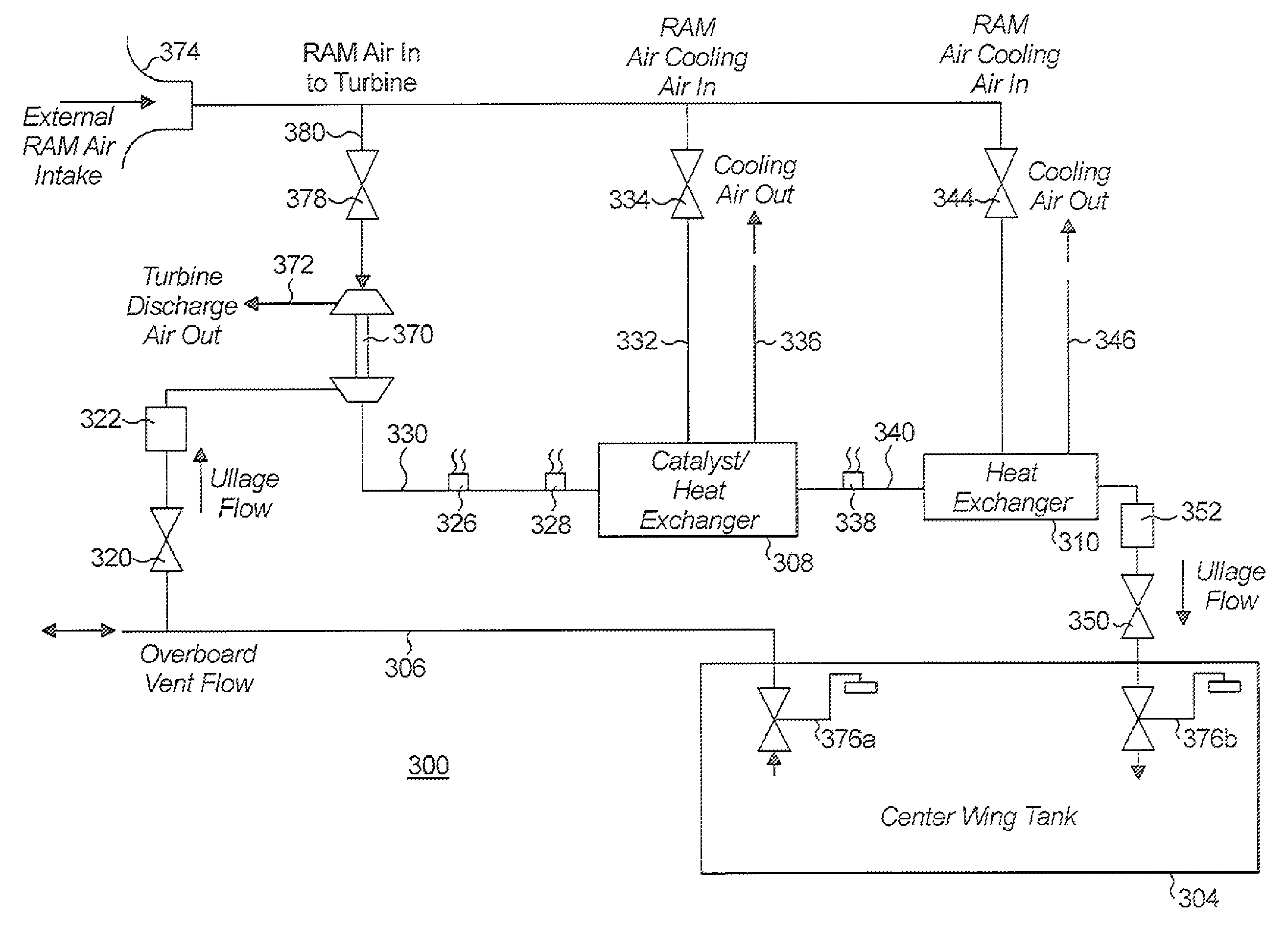
[0039]Turning to FIG. 3, another embodiment of an inerting system is indicated generally by the reference numeral 300. The inerting system 300 is similar to the inerting systems 100, 200 described above, and therefore like reference numerals preceded by the numeral “3” instead of the numeral “1” or “2”, respectively, are used to indicate like elements. The primary difference of the inerting system 300 in comparison to the systems 100, 200 is that the system 300 uses only ram air as the motive force to circulate the ullage. The following description is directed primarily to the differences of the system 300 in comparison to the systems 100, 200 for brevity.

[0040]Ram air is used to power a turbine (not shown explicitly), which in turn powers an air pump 370 to provide the motive force for ullage flow. The ram air comes from an air intake 374 and the turbine exhaust discharges through line 372. Preferably, the air intake 374 is a scoop which projects into the external airstream. Variou...

fourth embodiment

[0046]Referring now to FIG. 4, a portion of another embodiment for configuring a catalyst / heat exchanger 408 for use in an ullage inerting system is indicated generally by the reference numeral 400. As the inerting system 400 is similar to the inerting systems 100, 200, 300 described above, only a portion of the system 400 is shown. Like reference numerals preceded by the numeral “4” instead of the numeral “1”, “2” or “3”, respectively, are used to indicate like elements. The primary difference of the inerting system 400 is a small catalytic pre-heat chamber 480, which provides heat to the catalyst / heat exchanger 408 instead of electrical or engine bleed air pre-heating of the catalyst / heat exchanger 408. As a result, start up power requirements are reduced and the absorption of hydrocarbons from the ullage into the catalytic material in the catalyst / heat exchanger 408 is avoided.

[0047]It has been determined that allowing ullage to come in contact with the catalytic material while t...


PUM


Abstract

A system for reducing reactive components in ullage of a fuel tank, typically the fuel tank of an airplane. The system includes an air driven unit for creating a fluidic motive force to remove ullage from the fuel tank, and a main catalytic unit for receiving the ullage and reducing the reactive components to yield processed ullage for return to the fuel tank.

Description

BACKGROUND OF THE DISCLOSURE[0001]1. Field of the Disclosure[0002]The subject disclosure relates to systems for scavenging ullage from center wing tanks (CWT) in an airplane, and more particularly to an improved system for scavenging the ullage, then reducing the levels of reactive components, and returning the resulting inert air to the ullage space of the CWT.[0003]2. Background of the Related Art[0004]Center wing tanks (CWT) are used to hold fuel for airplanes. Although airplanes run on liquid fuel, the CWT generally contain some amount of air known as ullage. During long flights, for example, a large amount of fuel is consumed to create space in the CWT filled by ullage. If left alone, the ullage would not only be a gas rich in fuel vapors but include ample oxygen present in the ambient ullage air intake flow. When the ullage contains these reactive components (e.g., oxygen and / or fuel vapors), fires and explosions become possible.[0005]To alleviate the hazards associated with u...

Claims


Application Information

Patent Timeline
Patent Type & Authority Patents(United States)
IPC IPC(8): B64D37/04
CPCB64D37/24B64D37/32
Inventor BUCHWALD, PHILIP PAUL
Owner SIMMONDS PRECISION PRODS
Why Eureka
Try Eureka