Spherical annular seal member and method of manufacturing the same

a sealing member and annular seal technology, applied in the direction of cable terminations, machines/engines, mechanical equipment, etc., can solve the problems of exhaust system parts fatigue failure and aggravating the quietness of the vehicle compartment, so as to eliminate the generation of abnormal frictional noise, improve the retaining characteristic of solid lubricant, and eliminate the leakage of exhaust gases

Active Publication Date: 2013-12-10
OILES CORP
View PDF15 Cites 5 Cited by
  • Summary
  • Abstract
  • Description
  • Claims
  • Application Information

AI Technical Summary

Benefits of technology

[0026]In accordance with the invention, it is possible to provide a spherical annular seal member which is capable of eliminating the leakage of exhaust gases, of improving the retaining characteristic of the solid lubricant on the sliding surface, and of eliminating the generation of abnormal frictional noise, and which has stable sealing characteristics, as well as a method of manufacturing the same.
Advantages of the Invention

Problems solved by technology

Accordingly, there is a possibility of resulting in the fatigue failure of the exhaust system parts, and there are also cases where the vibration of the engine 606 causes the exhaust system parts to resonate, thereby aggravating the quietness of the vehicle compartment.

Method used


Image

  • Spherical annular seal member and method of manufacturing the same
  • Spherical annular seal member and method of manufacturing the same
  • Spherical annular seal member and method of manufacturing the same

Examples


example 1

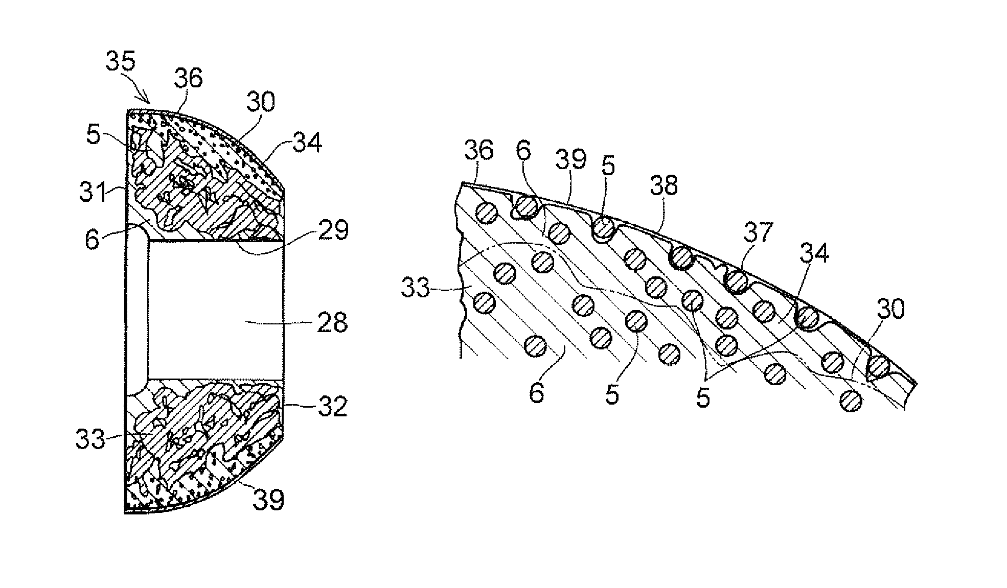
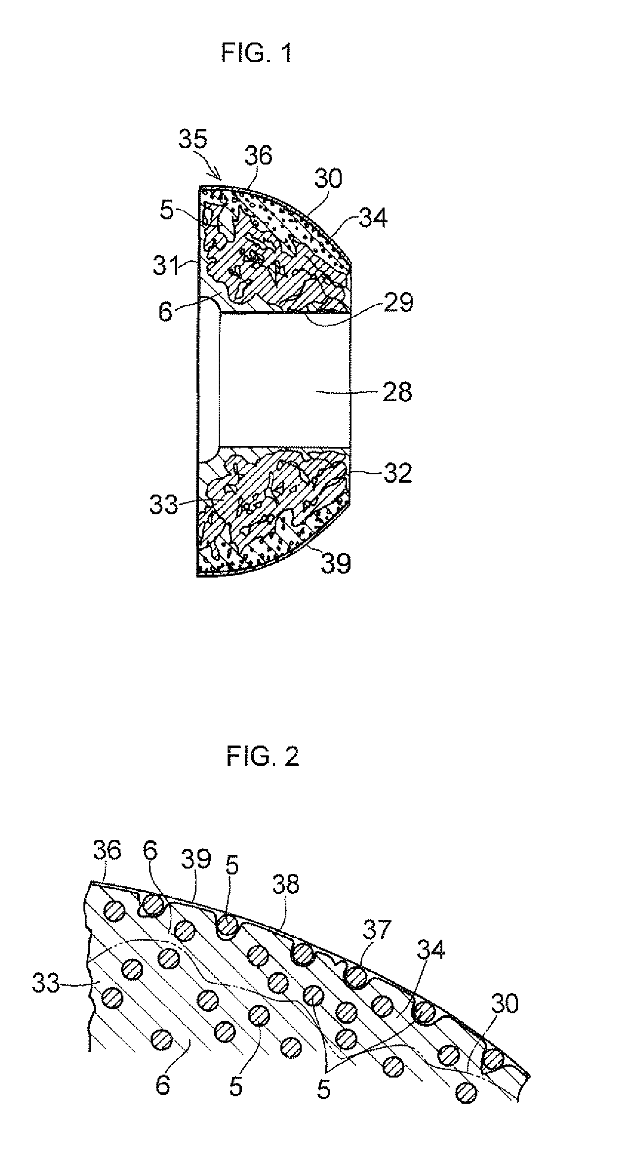
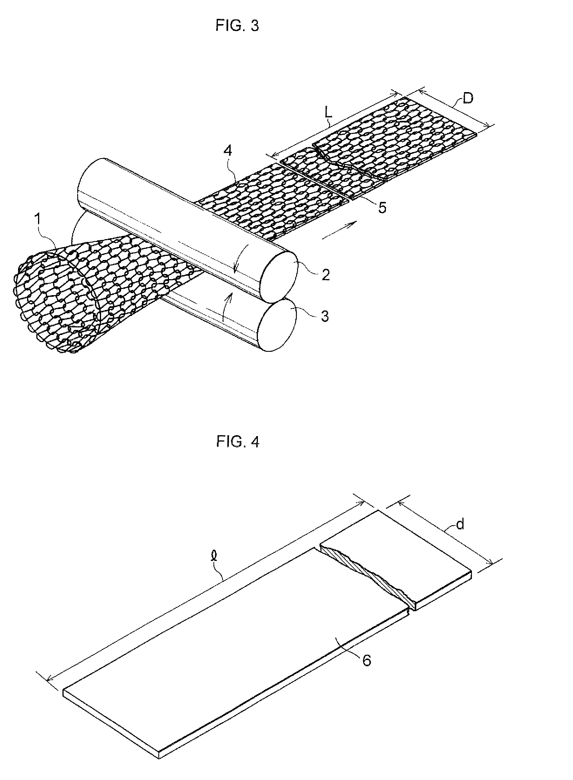
[0086]By using one austenitic stainless steel wire (SUS 304) having a wire diameter of 0.28 mm as a fine metal wire, a cylindrical braided metal wire net whose mesh size was 4 mm (vertical) and 5 mm (horizontal) was fabricated and was passed between a pair of rollers to form a belt-shaped metal wire net. The metal wire net thus formed was used as the reinforcing member for the spherical annular base member. As the heat-resistant material, an expanded graphite sheet containing 4.0 wt. % of aluminum primary phosphate and having a density of 1.12 Mg / m3 and a thickness of 0.4 mm was used. After the heat-resistant sheet member was spirally convoluted by a one-circumference portion, the reinforcing member was superposed on the inner side of the heat-resistant material, and the superposed assembly thereof was spirally convoluted, thereby preparing the tubular base member in which the heat-resistant material was exposed on the outermost periphery. In this tubular base member, widthwise oppo...

example 2

[0096]By using as fine metal wires two austenitic stainless steel wires which were similar to those of the above-described Example 1 and had a wire diameter of 0.28 mm, a cylindrical braided metal wire net whose mesh size was 4 mm (vertical) and 5 mm (horizontal) was fabricated and was passed between a pair of rollers to form a belt-shaped metal wire net. The metal wire net thus formed was used as the reinforcing member for the spherical annular base member. As the heat-resistant material, an expanded graphite sheet similar to that of the above-described Example 1 was used. After the heat-resistant sheet member was spirally convoluted by a one-circumference portion, the reinforcing member was superposed on the inner side of the heat-resistant material, and the superposed assembly thereof was spirally convoluted, thereby preparing the tubular base member in which the heat-resistant material was exposed on the outermost periphery. In this tubular base member, widthwise opposite end po...

example 3

[0105]A tubular base member was fabricated by using materials and a method similar to those of the above-described Example 1. In this tubular base member, widthwise opposite end portions of the heat-resistant material respectively projected (jutted out) from the reinforcing member in the widthwise direction.

[0106]A belt-shaped metal wire net was fabricated in the same way as in the above-described Example 1, and this belt-shaped metal wire net was used as the reinforcing member for the outer layer.

[0107]By using a heat-resistant material similar to the above-described heat-resistant material, a heat-resistant material having a smaller width than the width of the belt-shaped metal wire net of the reinforcing member for the outer layer was prepared separately.

[0108]An alumina sol similar to that of the above-described Example 1 was prepared. An aqueous dispersion (41.5 wt. % of h-BN, 2 wt. % of boron oxide, 6.5 wt. % of boehmite, and 50 wt. % of water and nitric acid) was then prepare...


PUM

PropertyMeasurementUnit
temperatureaaaaaaaaaa

Abstract

A spherical annular base member 33 is constructed such that a heat-resistant material 6 and a reinforcing member 5 are compressed and intertwined with each other so as to be provided with structural integrity. In an outer layer 34, a heat-resistant material 6, a solid lubricant constituted of a lubricating composition, and a reinforcing member 5 made from a metal wire net are compressed such that the solid lubricant and the heat-resistant material 6 are filled in meshes of the metal wire net of the reinforcing member 5, and the solid lubricant, the heat-resistant material 6, and the reinforcing member 5 are integrally formed in mixed form. An outer surface 36 of the outer layer 34 is formed into a smooth surface 39 in which a surface 37 constituted of the reinforcing member 5 and a surface 38 constituted by the solid lubricant are present in mixed form.

Description

[0001]This application is the U.S. national phase of International Application No. PCT / JP2008 / 003610, filed 4 Dec. 2008, which designated the U.S. and claims priority to Japanese Patent Application No. 2007-315273, filed 5 Dec. 2007, the entire contents of each of which are hereby incorporated by reference.TECHNICAL FIELD[0002]The present invention relates to a spherical annular seal member used in a spherical pipe joint for an automobile exhaust pipe, as well as a method of manufacturing the same.BACKGROUND ART[0003][Patent document 1] JP-B-58-21144[0004][Patent document 2] JP-A-58-34230[0005][Patent document 3] JP-B-3139179[0006]As shown in FIG. 16, exhaust gases from an automobile engine are generally led to an exhaust manifold 600 and are released from a tail pipe 605 into the atmosphere through a catalytic converter 601, an exhaust pipe 602, a prechamber 603, and a silencer 604. These exhaust system parts are repeatedly subjected to stress by the rolling behavior and vibration ...

Claims


Application Information

Patent Timeline
Patent Type & Authority Patents(United States)
IPC IPC(8): F16J15/32C10M125/26C10M147/02F01N13/08F01N13/16F01N13/18F16J15/12F16L23/02F16L23/16
CPCF01N13/08F01N13/16F01N13/1811F01N13/1827F01N13/1844F16J15/126F16L55/0337F16L27/053F16L27/073F01N2310/14
Inventor MAEDA, TAKASHIKUBOTA, SHUICHIFURUKIDO, TAKESHINISHIO, TOSHIYUKI
Owner OILES CORP
Why Eureka
Try Eureka