Audio effects controller for musicians

a technology for audio effects and controllers, applied in the field of audio effects controllers for musicians, can solve problems such as calibration, and achieve the effect of less rf power

Active Publication Date: 2013-12-17
CLEANSTAGE
View PDF47 Cites 22 Cited by
  • Summary
  • Abstract
  • Description
  • Claims
  • Application Information

AI Technical Summary

Benefits of technology

[0017]For a more integrated embodiment that makes use of other wireless needs for many musician or vocalists, the foot controller wirelessly communicates with a wireless repeater or Relay Body Pack worn by the performer, which relays this information wirelessly in addition to the audio signals generated by the musician. This embodiment thereby reduces the total number of wireless receivers for both systems from two to one, plus it has the advantage in that the foot controller requires less RF power due to its close proximity to the Relay Body Pack, and is not subjected to as much signal loss due to what would be normally seen without using the Relay Body Pack (as in the case of the performer walking behind objects on stage). The audio effect could also be integrated into the Relay Body Pack so that the resulting audio signal is already modulated before being sent Base Unit, and the Relay Body Pack could manage foot signal conditioning, where power is more abundant than what is practical in the foot controller.
[0018]Short vibrations within the shoe from a vibrating motor ( ) provides user feedback for either confirmation of a user control action or to help distinguish user foot commands through independent foot movements of a multi-stage control pattern.
[0020]Finally, the insole embodiment can be mirrored for a left shoe versus the right shoe ( ). In this assembly, a matching blank soul (with limited or no electronics) would be provided so that the left and right shoes would have the same feel. There is optionally a dual soul embodiment that utilizes both left and right foot controllers either independently for separate control use cases or in unison for combining left and right foot motion and pressure data to offer a wider range of control capability over a single sole system.

Problems solved by technology

However, there are undesirable characteristics of an FSR and other sensor types and enclosures, as well as variability from one musician to another (such as the fit of the footwear, user weight, or user habits), that may require calibration to be described in further detail.

Method used


Image

  • Audio effects controller for musicians
  • Audio effects controller for musicians
  • Audio effects controller for musicians

Examples


Embodiment Construction

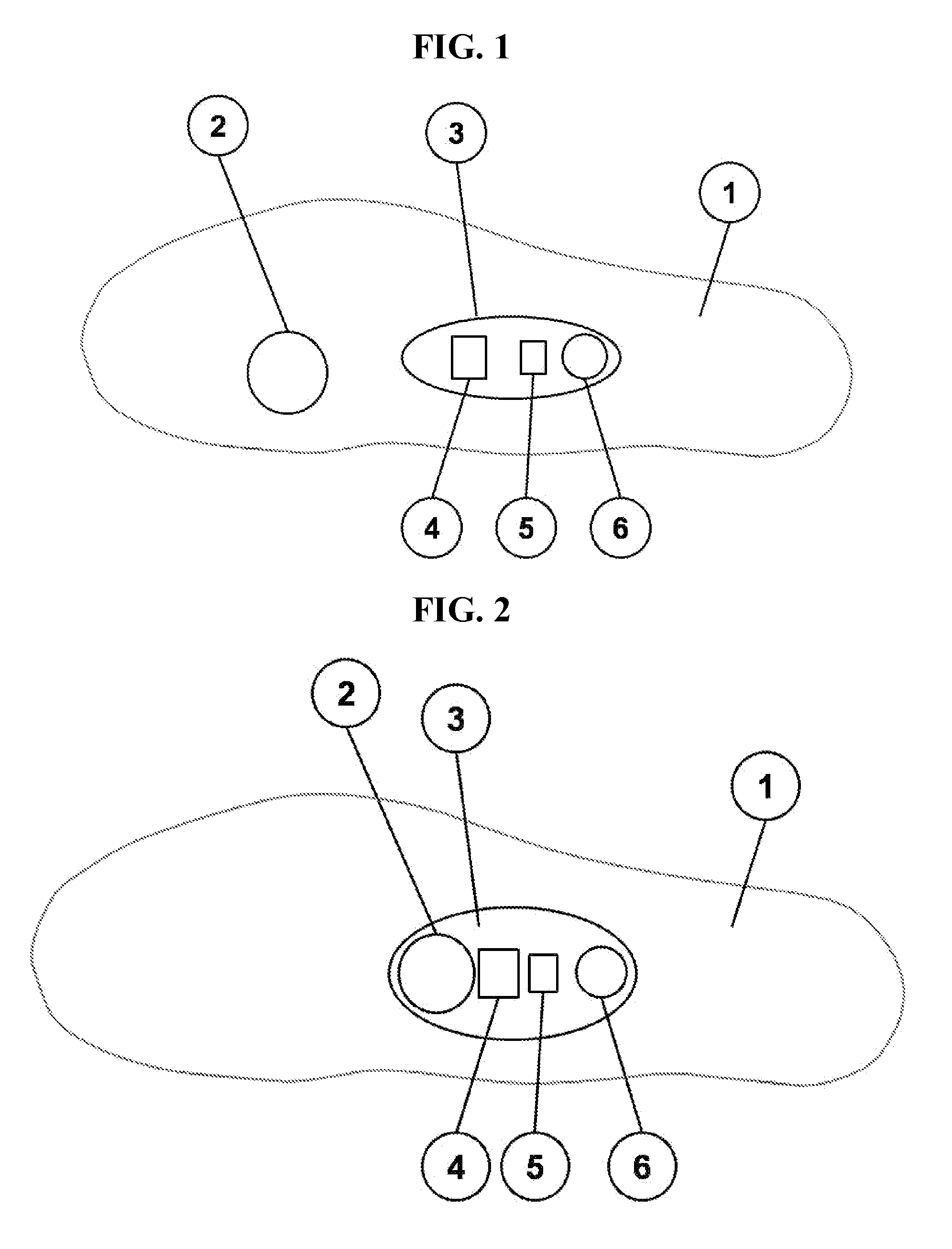
[0038]FIG. 1 shows Pressure Sensor (2) which senses foot pressure and is used by a musician to create a variable control signal for modulating audio effects while playing an electronic instrument such as a guitar, drums, a wearable keyboard, or even microphone amplified sources such as voice, harmonica, acoustic guitar, or any microphone amplified acoustic instrument.

[0039]Sole (1) of FIGS. 1 and 2 describe the general area under the feet and represent either the sole of the footwear, an insole, or the shoe bottom.

[0040]In FIG. 1, the main embodiment employs an FSR (2) (Force Sensing Resistor) and there are many types beyond the standard carbon-ink based products. In the prototype, a 100 lb range FSR was used, however, a 25 lb rating might offer more sensitivity depending on overall construction affecting the applied force at the sensor. FSR sensors typically require a few grams of force to start any change in resistance. Because of the protective cover and distribution of the user'...


PUM


Abstract

This invention introduces several methods, apparatus, and systems for controlling musician audio effects or musical instruments wirelessly from the performer's footwear. In one embodiment, the performer's foot motions are monitored using a motion detection device and compared against a set of criteria by a microprocessor to activate or deactivate one or more audio effects that are ready or “armed.” Once the foot controller is activated, a radio transmits sampled foot pressure that is used by the Base Unit to modulate all armed audio effects capable of being modulated. Tactile feedback is provided in the footwear as a means to confirm system status changes.

Description

[0001]Priority filing of U.S. Provisional Patent No. 61 / 413,683 filed Nov. 15, 2010 is claimed. Said provisional patent application is hereby incorporated by reference in its entirety into the present disclosure.BACKGROUND[0002]For today's experienced musician, an expression pedal such as a wah-wah, volume, (or others that use a rocking type mechanism controlled by the foot), are as common as the music from the 60's where many of these effects were born. Conventional use of the foot or feet by any member of the musician family of artists, in addition to the population of pedal or pad type users (in various industries, activities, games or sports) is well defined. For the musician population, this includes operation of variable electronic controls such as an expression-type pedal used by guitarists, physical type pedals used by percussionists, sustain or organ pedals used by keyboardists, and so on. Other existing uses of the feet include control of one or more pedals activated by on...

Claims


Application Information

Patent Timeline
Patent Type & Authority Patents(United States)
IPC IPC(8): G10H1/32G10H3/00
CPCG10H1/32G10H1/0083G10H1/348G10H2210/155G10H2210/231G10H2220/336G10H2220/395
Inventor D'AMOURS, JOHN ROBERT
Owner CLEANSTAGE
Why Eureka
Try Eureka