Distributed Coupling High Efficiency Linear Accelerator

Inactive Publication Date: 2014-07-10
THE BOARD OF TRUSTEES OF THE LELAND STANFORD JUNIOR UNIV
View PDF0 Cites 8 Cited by
  • Summary
  • Abstract
  • Description
  • Claims
  • Application Information

AI Technical Summary

Benefits of technology

[0007]Embodiments of this invention allow for the simple realization of the efficient π-mode structure without the drawbacks mentioned above. We eliminate the need for either the types of coupling cavities by, in the first embodiment of this invention feeding each cavity by a compact directional coupler, and in the second embodiment by a symmetrical distribution system. The RF coupling in either case has no resonant structures and hence is highly efficient.
[0008]In the first case it also provides an implementation of ideas proposed by one of the inventors, and for which the reflection to the source is eliminated. The second implementation has all the waveguide in the distribution system oriented such that the small dimensions of the waveguide oriented along the accelerator structures radial direction. This orientation minimizes the structure volume and complexity, allowing for lighter and more compact implementation.
[0009]According to one embodiment, a microwave circuit is provided having compact, tolerance insensitive, directional couplers, compact E-plane bends, and multiple azimuthal feeds from a single feed.
[0010]According to another embodiment, a microwave circuit is provided having a distribution waveguide with its width designed to provide appropriate phase shift between feed arms, where each of the feed arms has two slots feeding two separate short accelerator sections (e.g., each section may have four cavities), where two slots in each feed arm provide a natural 180 degree phase shift between the two fed accelerator section due to the nature of the fundamental mode in the waveguide representing these feed arms. This is ideal for the efficient π-mode accelerator structure. The short circuit length

Problems solved by technology

The theoretical idea of feeding each cavity is old; however, until now there has been no practical implementation that allows such topology to exist.
This was previously thought to be impractical due to the required size of the directional couplers, microwave bends and RF loads needed to implement the circuit which all has to fit within the distance between two adjacent cells.
However, this can only work for a small number of cells because of the mode density problems associated with small coupling between cells—a feature required for efficient operation.
T

Method used


Image

  • Distributed Coupling High Efficiency Linear Accelerator
  • Distributed Coupling High Efficiency Linear Accelerator
  • Distributed Coupling High Efficiency Linear Accelerator

Examples


Embodiment Construction

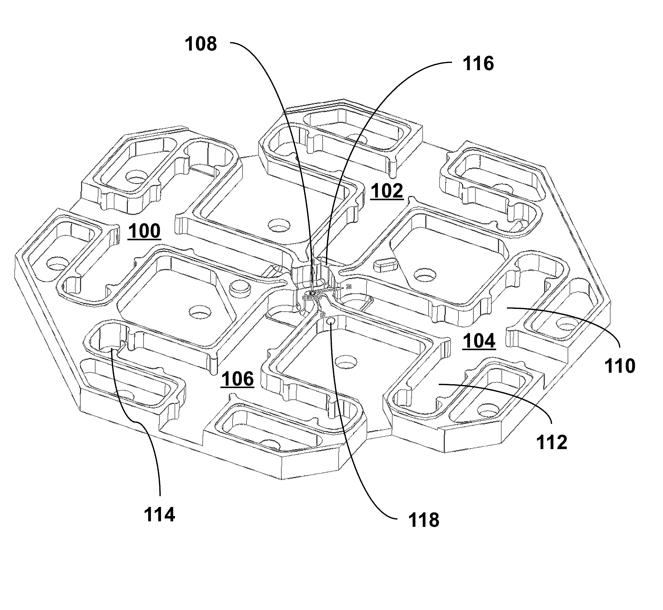
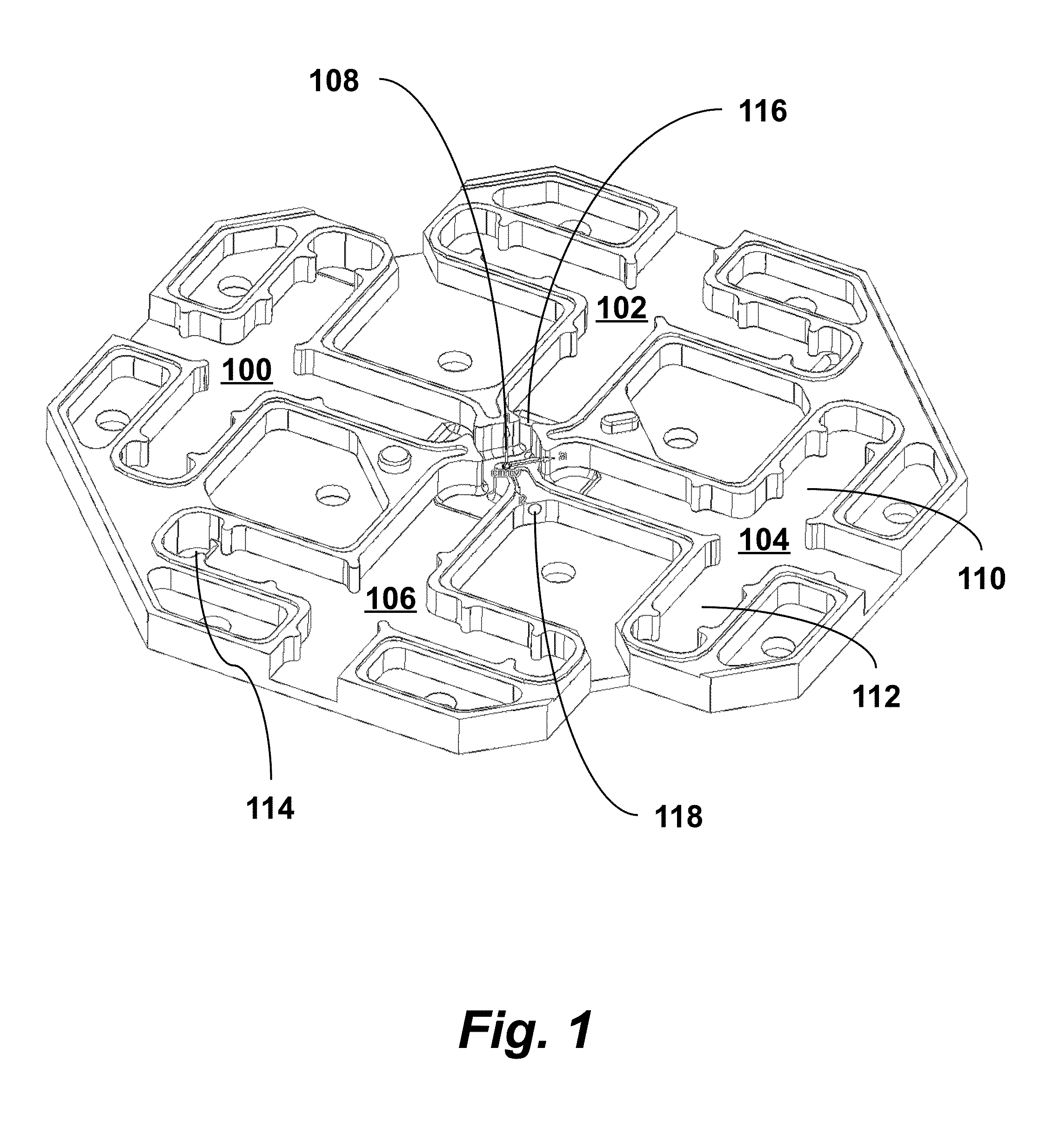
[0022]FIG. 1 is an illustration of a monolithic metallic linac cell plate according to an embodiment of the invention. A microwave circuit for a linear accelerator may be formed by stacking multiple such cell plates upon each other. The cell has four cross-shaped directional couplers 100, 102, 104, 106 symmetrically oriented around an acceleration cavity 108 that is aligned with a vertical beam axis of the linear accelerator. Each directional coupler 100, 102, 104, 106 has coupling arms. For example, coupler 104 has arms 110 and 112. Each coupling arm has an in-plane width less than an operational wavelength of the linear accelerator. Each of the cell plates has one or more coupling slots, such as slot 114, that couples one of the directional couplers in the cell to an adjacent directional coupler of an adjacent cell. Each of the cell plates also has one or more coupling slots, such as slot 116, that couples the directional coupler to the central acceleration cavity 108. The cell pl...


PUM


Abstract

A microwave circuit for a linear accelerator includes multiple monolithic metallic cell plates stacked upon each other so that the beam axis passes vertically through a central acceleration cavity of each plate. Each plate has a directional coupler with coupling arms. A first coupling slot couples the directional coupler to an adjacent directional coupler of an adjacent cell plate, and a second coupling slot couples the directional coupler to the central acceleration cavity. Each directional coupler also has an iris protrusion spaced from corners joining the arms, a convex rounded corner at a first corner joining the arms, and a corner protrusion at a second corner joining the arms.

Description

CROSS-REFERENCE TO RELATED APPLICATIONS[0001]This application is a continuation-in-part of U.S. patent application Ser. No. 13 / 947043 filed Jul. 20, 2013, which claims priority from U.S. Provisional Patent Application 61 / 674262 filed Jul. 20, 2012, both of which are incorporated herein by reference.STATEMENT OF GOVERNMENT SPONSORED SUPPORT[0002]This invention was made with Government support under contract DE-AC02-76SF00515 awarded by Department of Energy. The Government has certain rights in this invention.FIELD OF THE INVENTION[0003]The present invention relates generally to linear accelerators. More specifically, it relates to improved microwave linear accelerators.BACKGROUND OF THE INVENTION[0004]A linear particle accelerator (linac) accelerates charged particles using a series of oscillating electric potentials generated by RF cells joined together to form a linear beamline. At one end of the linac, the particles from a particle source are injected into the beamline using a hig...

Claims


Application Information

Patent Timeline
IPC IPC(8): H05H9/04
CPCH05H9/044H05H7/02H05H7/18H05H9/04
Inventor TANTAWI, SAMI G.NEILSON, JEFFREY
Owner THE BOARD OF TRUSTEES OF THE LELAND STANFORD JUNIOR UNIV
Why Eureka
Try Eureka