Method for hydrocarbon recovery using a water changing or driving agent with RF heating

a technology of hydrocarbon resources and heating, applied in fluid removal, earth-moving drilling, borehole/well accessories, etc., can solve the problems of high viscosity hydrocarbon resources, heavy oils, and energy consumption of conventional hydrocarbon resources, and achieve the effect of efficient recovery of hydrocarbon resources, less energy, and faster recovery of hydrocarbons

Active Publication Date: 2014-04-17
HARRIS CORP
View PDF3 Cites 5 Cited by
  • Summary
  • Abstract
  • Description
  • Claims
  • Application Information

AI Technical Summary

Benefits of technology

[0013]In view of the foregoing background it is therefore an object of the present invention to provide a method for more efficiently recovering hydrocarbon resources from a subterranean formation while potentially using less energy and providing faster recovery of the hydrocarbons.

Problems solved by technology

Energy consumption worldwide is generally increasing, and conventional hydrocarbon resources are being consumed.
For example, highly viscous hydrocarbon resources, such as heavy oils, may be trapped in tar sands where their viscous nature does not permit conventional oil well production.
The SAGD process may be relatively sensitive to shale streaks and other vertical barriers since, as the rock is heated, differential thermal expansion causes fractures in it, allowing steam and fluids to flow through.
Oil is not yet produced from oil sands on a significant level in other countries.
Unfortunately, long production times to extract oil using SAGD may lead to significant heat loss to the adjacent soil, excessive consumption of steam, and a high cost for recovery.
Moreover, there may be an insufficient amount of caprock to contain the steam, and surface water resources may be limited.
However, conducted heating is relatively slow and unreliable.
Also, many SAGD wells fail to start, and SAGD may be impractical in permafrost areas due to melting at the surface.
Unfortunately, SAGD may not efficiently permit recovery of the hydrocarbon resources in that SAGD may have increased capital and energy costs, for example, as disclosed in U.S. Patent Application Publication No. 2010 / 0276148 to Wylie et al.

Method used


Image

  • Method for hydrocarbon recovery using a water changing or driving agent with RF heating
  • Method for hydrocarbon recovery using a water changing or driving agent with RF heating
  • Method for hydrocarbon recovery using a water changing or driving agent with RF heating

Examples


Embodiment Construction

[0032]The present invention will now be described more fully hereinafter with reference to the accompanying drawings, in which preferred embodiments of the invention are shown. This invention may, however, be embodied in many different forms and should not be construed as limited to the embodiments set forth herein. Rather, these embodiments are provided so that this disclosure will be thorough and complete, and will fully convey the scope of the invention to those skilled in the art. Like numbers refer to like elements throughout, and prime and multiple prime notation is used to indicate similar elements in alternative embodiments.

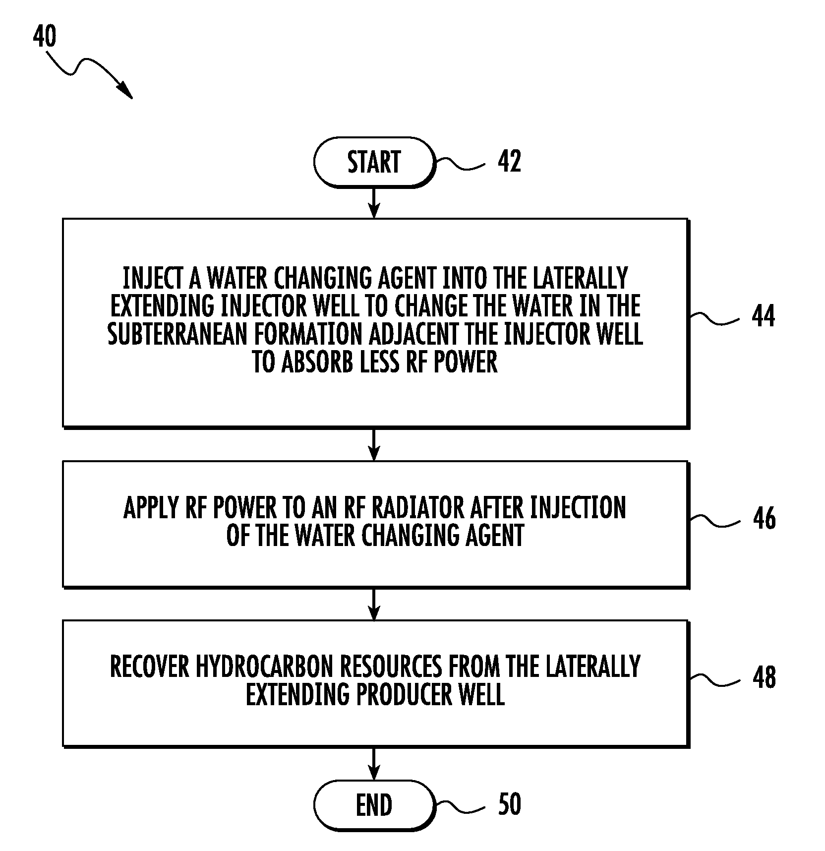
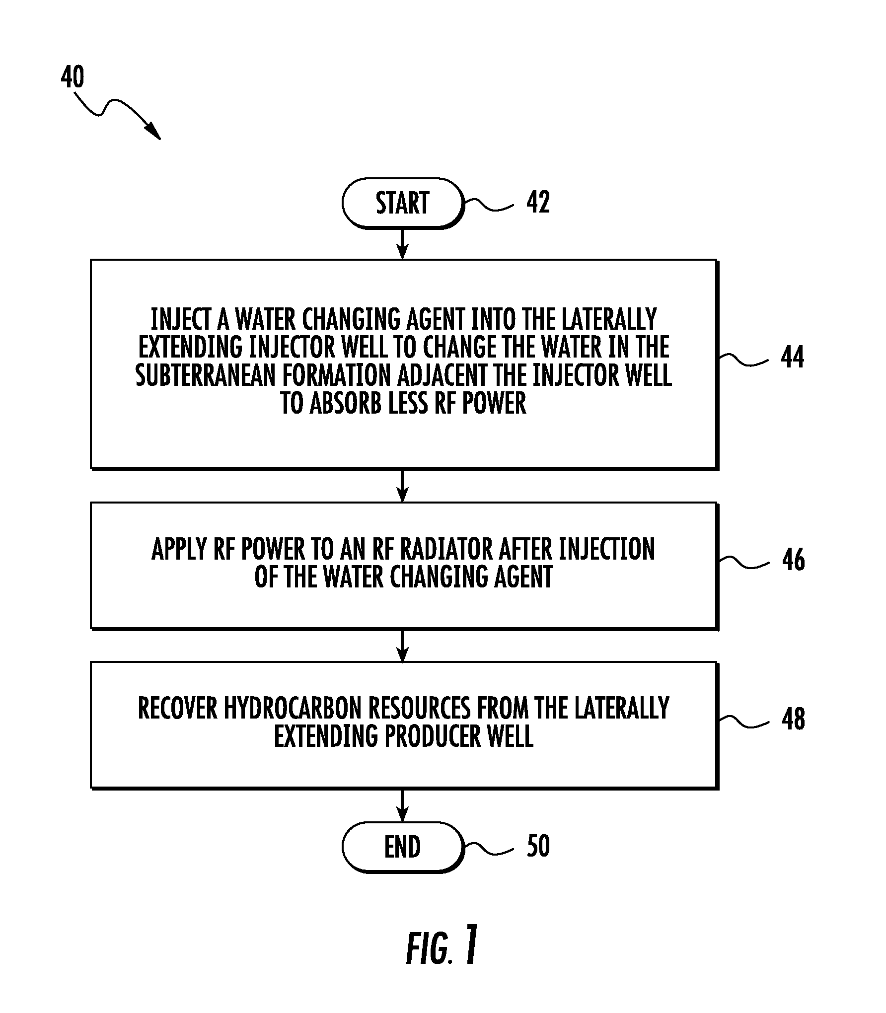
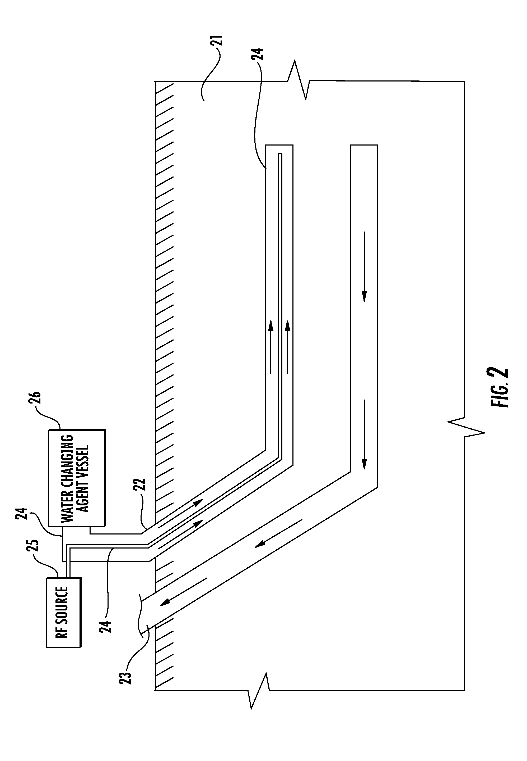
[0033]Referring now to the flowchart 40 in FIG. 1 and FIG. 2, a method of processing a hydrocarbon resource in a subterranean formation 21 is illustrated. The subterranean formation 21 includes a laterally extending injector well 22, a laterally extending producer 23 well below the laterally extending injector well. Water and hydrocarbon resources are wit...


PUM


Abstract

A method of processing a hydrocarbon resource in a subterranean formation including a laterally extending injector well, a laterally extending producer well below the laterally extending injector well, and water within the subterranean formation, may include injecting a water changing agent into the laterally extending injector well to change the water in the subterranean formation adjacent the injector well to absorb less RF power. The method may also include applying RF power to an RF radiator within the injector well after injection of the water changing agent, and recovering hydrocarbon resources from the laterally extending producer well. In another embodiment, the method may include injecting a water driving agent into the laterally extending injector well.

Description

FIELD OF THE INVENTION[0001]The present invention relates to the field of hydrocarbon resource recovery, and, more particularly, to hydrocarbon resource recovery using RF heating.BACKGROUND OF THE INVENTION[0002]Energy consumption worldwide is generally increasing, and conventional hydrocarbon resources are being consumed. In an attempt to meet demand, the exploitation of unconventional resources may be desired. For example, highly viscous hydrocarbon resources, such as heavy oils, may be trapped in tar sands where their viscous nature does not permit conventional oil well production. Estimates are that trillions of barrels of oil reserves may be found in such tar sand formations.[0003]In some instances these tar sand deposits are currently extracted via open-pit mining. Another approach for in situ extraction for deeper deposits is known as Steam-Assisted Gravity Drainage (SAGD). The heavy oil is immobile at reservoir temperatures and therefore the oil is typically heated in-situ t...

Claims


Application Information

Patent Timeline
Patent Type & Authority Applications(United States)
IPC IPC(8): E21B43/24
CPCE21B43/20E21B43/2401E21B43/2408
Inventor PARSCHE, FRANCIS E.
Owner HARRIS CORP
Why Eureka
Try Eureka