Optical position detection device, optical position detection system, and display system with input function

a technology of optical position detection and display system, which is applied in the direction of navigation instruments, instruments for comonautical navigation, instruments, etc., can solve the problems of large attenuation, narrow range where the position of the target object can be detected, and large attenuation

Inactive Publication Date: 2013-12-17
COLUMBIA PEAK VENTURES LLC
View PDF10 Cites 3 Cited by
  • Summary
  • Abstract
  • Description
  • Claims
  • Application Information

AI Technical Summary

Benefits of technology

[0011]In the optical position detection device according to the aspect of the invention, it is preferable that an emission angle range of the first detection light in the third direction be narrower than an emission angle range of the second detection light in the third direction. According to this configuration, even when the distance between the first and second light source modules in the third direction is small, an overlapping portion of the first detection light and the second detection light in the third direction can be made narrow. Therefore, even when the distance between the first and second light source modules in the third direction is small, the position of the target object in the third direction can be reliably detected.
[0013]In the optical position detection device according to the aspect of the invention, preferably, the emission angle range limiting member is a louver film and a louver portion of the louver film is inclined toward a side opposite to a side at which the second light source module is located in the third direction from a light incidence surface toward a light emitting surface of the louver film. According to this configuration, the amount of overlap between the first detection light and the second detection light can be reduced.
[0016]In the optical position detection device according to the aspect of the invention, preferably, the position detecting section detects a position of the target object in the first and second directions on the basis of a comparison result of a received light intensity in the first period and a received light intensity in the second period in the light receiving section, and detects the position of the target object in the third direction on the basis of a comparison result of the received light intensity in the third period and the received light intensity in the fourth period in the light receiving section. According to this configuration, the influence of ambient light, such as outside light, and the like can be eliminated.

Problems solved by technology

In the optical position detection devices disclosed in JP-T-2003-534554, JP-A-2010-127671, and JP-A-2009-295318, however, there is a problem in that the range where the position of the target object can be detected is narrow.
However, if the large light guide plate is used, large attenuation occurs when detection light propagates through the light guide plate.
For this reason, since it is difficult to form a predetermined light intensity distribution with a sufficient intensity level over a wide range, the range where the position of the target object can be detected is narrow.
In this case, however, since the emission angle range of the detection light emitted from the light source sections is narrow, the range where the position of the target object can be detected becomes extremely narrow.
It is difficult to form such an intensity distribution with a large light guide plate.
Therefore, the range where the position of the target object can be detected is extremely narrow.

Method used


Image

  • Optical position detection device, optical position detection system, and display system with input function
  • Optical position detection device, optical position detection system, and display system with input function
  • Optical position detection device, optical position detection system, and display system with input function

Examples


first embodiment

Overall Configuration

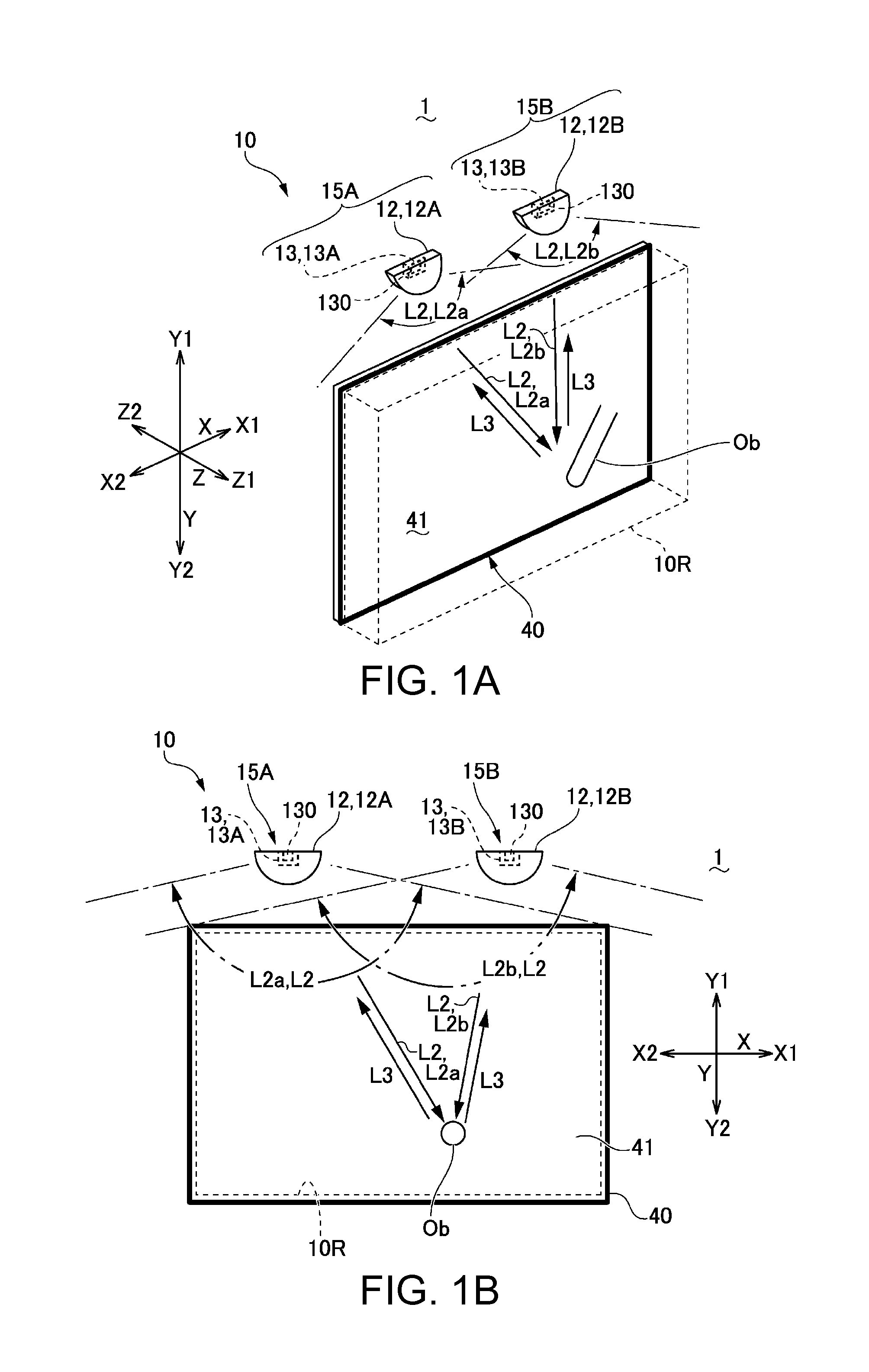
[0039]FIGS. 1A and 1B are explanatory views schematically showing sections of an optical position detection device according to a first embodiment of the invention. FIG. 1A is an explanatory view when the optical position detection device is viewed from the oblique direction at the side of a detection light emission space, and FIG. 1B is an explanatory view when the optical position detection device is viewed from the front.

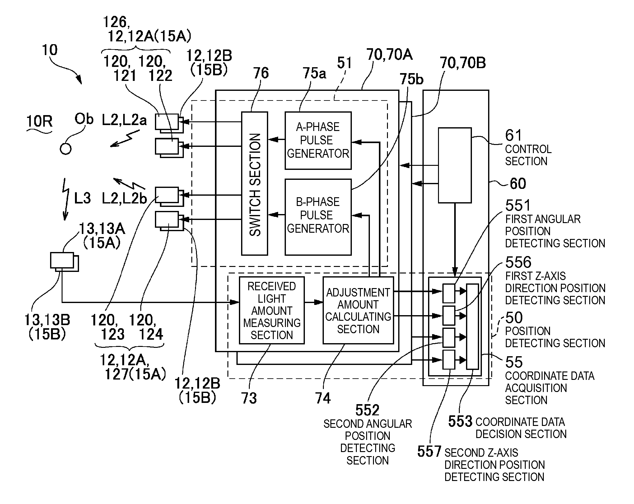
[0040]In FIGS. 1A and 1B, a position detection system 1 according to the present embodiment includes an optical position detection device 10 which detects the position of a target object Ob. The optical position detection device 10 detects the position of the target object Ob using detection light L2 which is radially emitted along the virtual XY plane (virtual plane) defined by the X-axis direction and the Y-axis direction. In the present embodiment, the position detection system 1 includes a viewing surface forming member 40 having a viewin...

second embodiment

Configuration of a Light Emission and Reception Unit

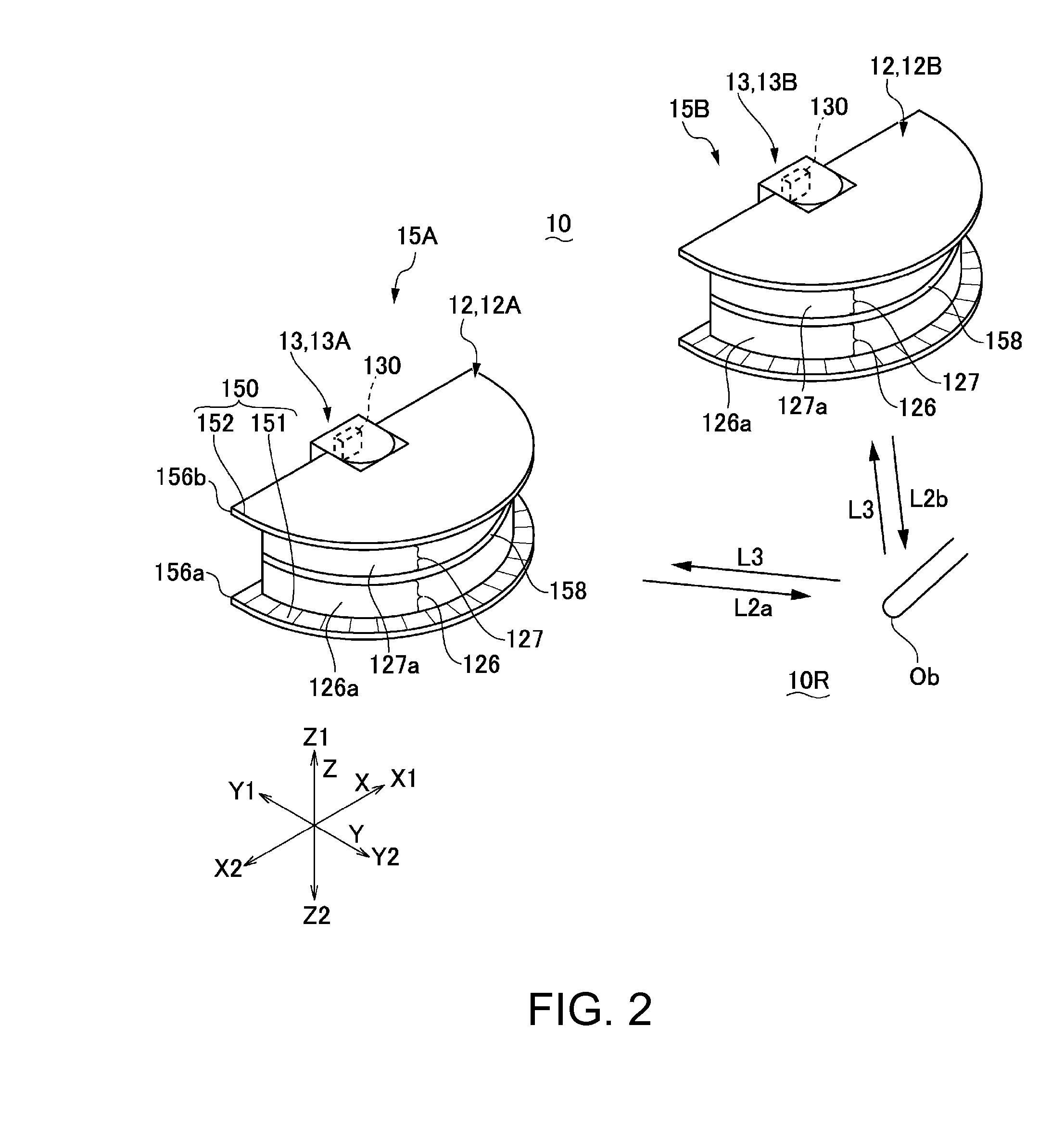
[0097]FIG. 12 is an explanatory view of a light emission and reception unit of an optical position detection device 10 according to a second embodiment of the invention. In addition, since the basic configuration in the present embodiment is the same as that in the first embodiment, the same components are denoted by the same reference numerals, and a duplicate explanation thereof will be omitted.

[0098]Although the light guide LG is used in the light source section 12 in the first embodiment, the XY coordinate of the target object Ob is detected in the same way as the first embodiment without using a light guide in the present embodiment. More specifically, as shown in FIG. 12, each of the light source sections 12 (first and second light source sections 12A and 12B) of the optical position detection device 10 according to the present embodiment includes the plurality of light emitting elements 120 distributed in an array in the cir...


PUM


Abstract

In an optical position detection device, the XY coordinates of a target object are detected based on received light intensity of a light receiving section by forming a light intensity distribution, in which the intensity changes in a radiation angle range of detection light, with first and second light source modules. The first and second light source modules are separated from each other in the Z-axis direction, and the position of the target object in the Z-axis direction is detected based on the received light intensity of the light receiving section when forming the light intensity distribution in which the intensity is fixed in the radiation angle range of detection light.

Description

BACKGROUND[0001]1. Technical Field[0002]The present invention relates to an optical position detection device which optically detects the position of a target object, an optical position detection system, and a display system with an input function.[0003]2. Related Art[0004]An optical position detection device has been proposed to detect a target object. In such a device, a plurality of point light source sections and a plurality of light receiving sections are provided at positions separated from each other. When detection light is emitted from each of the light source sections toward a target object through a light transmissive member, detection light reflected from the target object is transmitted through the light transmissive member and is then detected by the light receiving sections (refer to JP-T-2003-534554). The optical position detection device detects the position of the target object using a condition in which the received light intensity in a light receiving section ch...

Claims


Application Information

Patent Timeline
Patent Type & Authority Patents(United States)
IPC IPC(8): G06F3/042
CPCG06F3/0421
Inventor ONISHI, YASUNORI
Owner COLUMBIA PEAK VENTURES LLC
Why Eureka
Try Eureka