Method for manufacturing liquid discharge head substrate

a technology of liquid discharge head and substrate, which is applied in the direction of recording equipment, instruments, and record information storage, etc., can solve the problems of reducing the productivity of inkjet head substrate and prolonging the etching period, and achieve the effect of reducing the opening width of ink supply ports without adversely affecting productivity and strength

Inactive Publication Date: 2013-12-24
CANON KK
View PDF11 Cites 7 Cited by
  • Summary
  • Abstract
  • Description
  • Claims
  • Application Information

AI Technical Summary

Benefits of technology

[0012]While taking the above problems into account, one objective of the present invention is to provide an inkjet head substrate wherein the opening width of an ink supply port has been reduced without adversely affecting productivity and strength.
[0014]According to the present invention, since the opening width of the ink supply port of the head substrate is narrowed, the head substrate can be downsized and a discharge function better stabilized.

Problems solved by technology

However, when the amount of material to be removed by anisotropic dry etching is increased, the etching period is extended and inkjet head substrate productivity is reduced.

Method used


Image

  • Method for manufacturing liquid discharge head substrate
  • Method for manufacturing liquid discharge head substrate
  • Method for manufacturing liquid discharge head substrate

Examples


first embodiment

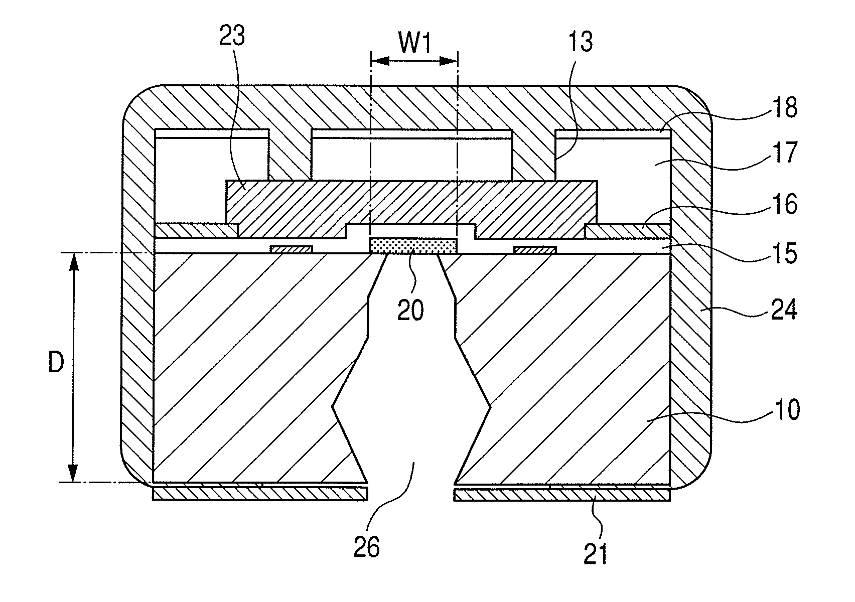
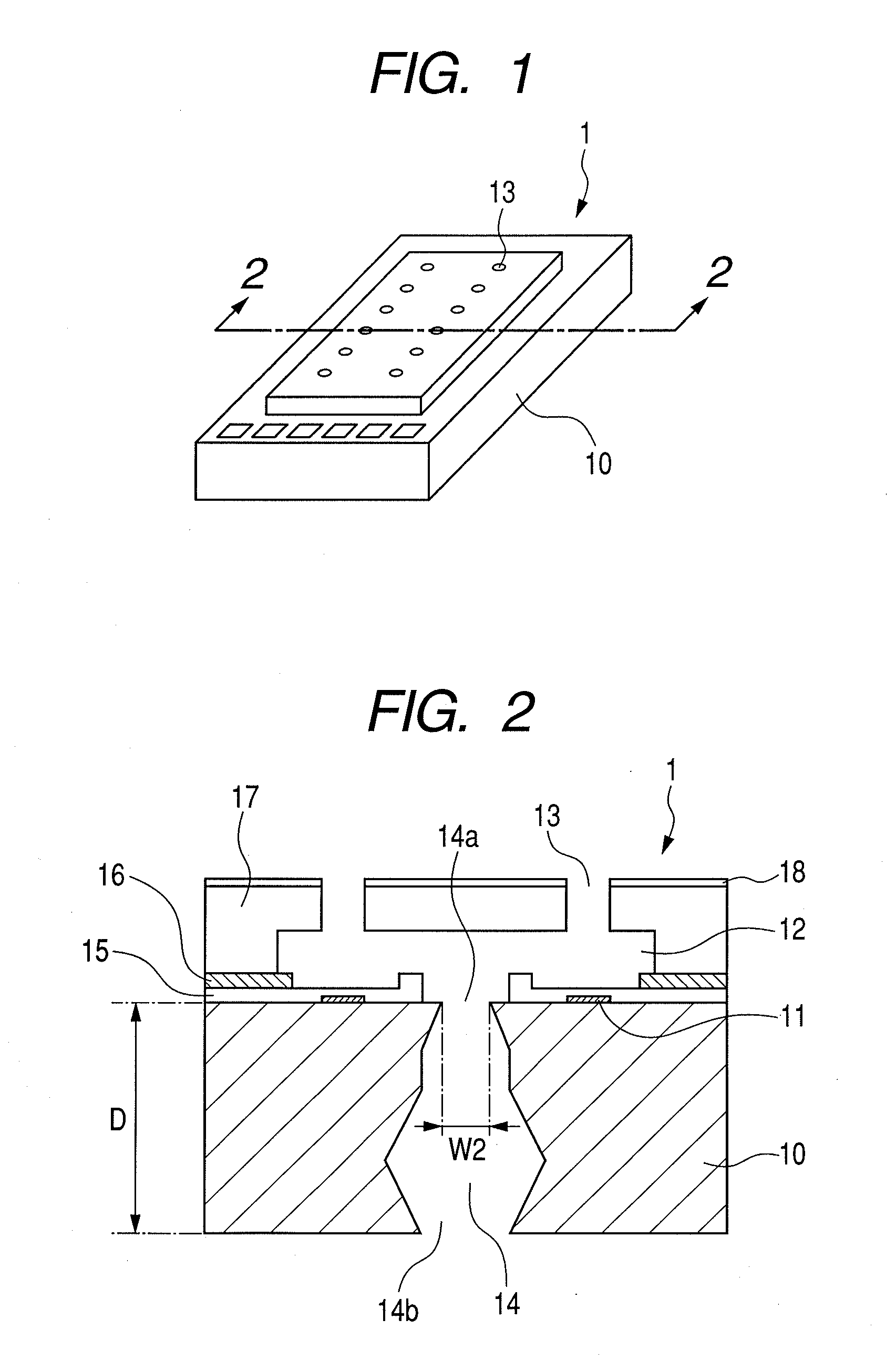
[0029]For the sake of convenience, a descriptive overview will be given for a liquid discharge head substrate produced using a liquid discharge head substrate manufacturing method of a first embodiment of this invention, and the structure of a liquid discharge head for which this substrate is employed. FIG. 1 is a schematic perspective view of an inkjet head substrate 1, an example liquid discharge head produced using the manufacturing method of the first embodiment. And FIG. 2 is a cross-sectional view of the inkjet head substrate 1 taken along line 2-2 in FIG. 1.

[0030]The inkjet head substrate 1 (hereinafter referred to also as a head substrate) includes a silicon substrate 10, on the obverse side of which are formed multiple energy generation elements 11, such as heaters, and ink flow passageways 12 and discharge ports 13. Further, an ink supply port 14 passes through the silicon substrate 10, opening out on both the obverse and reverse sides.

[0031]More specifically, the energy g...

second embodiment

[0057]A head substrate manufacturing method according to a second embodiment of the present invention will now be described while referring to FIGS. 5 and 6. FIG. 5 is a schematic cross-sectional view of the processing performed for the manufacturing method of the second embodiment. And FIG. 6 is a schematic cross-sectional view of a head substrate obtained by employing the manufacturing method of this embodiment.

[0058]The head substrate manufacturing method of this embodiment basically provides the same processing as the manufacturing method of the first embodiment. The only difference is the length of a period required for orientation-dependent anisotropic etching to form a recessed portion (a non-perforating hole) 26 that later becomes an ink supply port 14. Specifically, as illustrated in FIG. 5, orientation-dependent anisotropic etching is performed for a shorter period than in the first embodiment, and a second recessed portion 26 is formed. As a result, as illustrated in FIG....

third embodiment

[0059]A head substrate manufacturing method according to a third embodiment of the present invention will now be described while referring to FIGS. 7 and 8. FIG. 7 is a schematic cross-sectional view of the processing performed by the manufacturing method of the third embodiment, and FIG. 8 is a schematic cross-sectional view of a head substrate obtained using the manufacturing method of the embodiment.

[0060]The head substrate manufacturing method of this embodiment provides the same processing as that of the first embodiment. The only difference is that the anisotropic etching process is performed in three steps to form a recessed portion (a non-perforating hole) 26 that will later be an ink supply port 14.

[0061]Specifically, according to the manufacturing method of the first embodiment, orientation-dependent anisotropic wet etching and anisotropic dry etching have been performed for the silicon substrate 10, in the named order, to form the second recessed portion 26. However, acco...


PUM

PropertyMeasurementUnit
widthaaaaaaaaaa
diameteraaaaaaaaaa
thicknessaaaaaaaaaa

Abstract

A manufacturing method, for a liquid discharge head substrate that includes a silicon substrate in which a liquid supply port is formed, includes the steps of: preparing the silicon substrate, on one face of which a mask layer, in which an opening has been formed, is deposited; forming a first recessed portion in the silicon substrate, so that the recessed portion is extended through the opening from the one face of the silicon substrate to the other, reverse face of the silicon substrate; forming a second recessed portion by performing wet etching for the substrate, via the first recessed portion, using the mask layer; and performing dry etching for the silicon substrate in a direction from the second recessed portion to the other face.

Description

BACKGROUND OF THE INVENTION[0001]1. Field of the Invention[0002]The present invention relates to a method for manufacturing a liquid discharge head substrate, to be employed for a liquid discharge head.[0003]2. Description of the Related Art[0004]Well known liquid discharge heads are the descriptively named inkjet heads that today are so often employed in printers to discharge ink. Generally, for such an inkjet head, a substrate is provided that includes: discharge ports, through which ink is to be discharged; energy generation elements, used to generate the energy required for the discharge of ink through the discharge ports; an ink supply port, to which and through which ink is to be supplied; and ink flow passageways, which communicate with the ink supply port and the discharge ports and along which ink is supplied to the discharge ports. The discharge ports, the energy generation elements and the ink flow passageways are arranged on the obverse face of the substrate, while the i...

Claims


Application Information

Patent Timeline
Patent Type & Authority Patents(United States)
IPC IPC(8): G01D15/00G11B5/127
CPCB41J2/1603B41J2/1623B41J2/1628B41J2/1629B41J2/1631B41J2/1634B41J2/1635B41J2/1639B41J2/1645
Inventor ASAI, KAZUHIROKOMURO, HIROKAZUIBE, SATOSHIHATSUI, TAKUYAOTAKA, SHIMPEIKOMIYAMA, HIROTOKISHIMOTO, KEISUKE
Owner CANON KK
Why Eureka
Try Eureka