Waste collection device, docking device and waste collection and disposal system

a waste collection and disposal system technology, applied in the direction of suction drainage containers, mechanical devices, cleaning using liquids, etc., can solve the problems of affecting the medical process, high cost, and complex structure of said structure, so as to improve the accuracy of docking and facilitate user-friendly operation, the effect of high fault tolerance to the position

Pending Publication Date: 2022-05-05
AMSINO MEDICAL (SHANGHAI) CO LTD
View PDF0 Cites 1 Cited by
  • Summary
  • Abstract
  • Description
  • Claims
  • Application Information

AI Technical Summary

Benefits of technology

[0007]The technical problem to be solved by the embodiments of the present invention is to provide a waste collection device that can automatically perform an alignment and complete the docking during the process of docking. The waste collection device has the advantage of simple structure and can save costs of both manufacturing and materials.
[0044]Further, the guide bayonet has an inner end with a curved surface, and two sides of wedge-shaped structures so that the opening width from the front end to the inner end of the bayonet is gradually reduced.
[0053]First of all, in the waste collection device according to the embodiment of the present invention, the docking end connectors of the docking device are first mated with the floating sleeve heads, and then the collection end connectors and the docking end connectors are coupled. After the docking end connector is inserted into the corresponding floating sleeve head, the floating sleeve head are floatingly movable to guide the docking end connector into the floating sleeve head, and the docking end connector is gradually aligned with the collection end connector. Due to the suspension movement of the floating sleeve head, the docking end connector will not cause an impact on the floating sleeve head and will also not bring about a displaced collision with the collection end connector to cause wear, even if the docking end connector and the floating sleeve head are not completely aligned. That is, in the process of the waste collection device being docked to the docking device, there can be a relatively high fault tolerance to position, which can not only improve the accurate rate of docking, but also facilitate user friendly operation, and at the same time it can also reduce the damage caused by the imprecise alignment between the collection end connectors and the docking end connectors.
[0054]Secondly, the waste collection device in the embodiments of the invention can have a simple and low complex structure for achieving position guidance and correction, which requires less raw materials, is easy to manufacture, and can reduce costs.

Problems solved by technology

Waste in a liquid, semi-solid, and solid form and the like is inevitably generated in the course of performing a specific surgery.
In a series of medical procedures, each procedure requires such an “emptying”, and such frequent operations that the waste collection device is pushed to the docking station each time will cause a lot of inconvenience to users and affect a medical process.
Said structure is complex, costs high, and the connectors can only be inserted after the docking device and the waste collection device are very accurately aligned, that is, the insertion operation of plugs can only be performed after the docking connectors of both the docking device and the waste collection device has completed an alignment before their contacts, and the operation of such alignment cannot be continued after the plug is in contact with the socket.
The structure not only requires a complicated alignment operation, but also increases the complexity and cost of the device.
At the same time, where a misalignment occurs, damage to the connectors will be caused due to the low fault-tolerant rate during the docking process of the two connectors of the docking device and the two connectors of the waste collection device.

Method used


Image

  • Waste collection device, docking device and waste collection and disposal system
  • Waste collection device, docking device and waste collection and disposal system
  • Waste collection device, docking device and waste collection and disposal system

Examples


Embodiment Construction

[0070]The description of the following embodiments is to illustrate specific implementable embodiments in the present disclosure with reference to accompanying drawings. The directional terms mentioned in the present disclosure, such as “upper”, “downward”, “front”, “rear”, “left”, “right”, “inner”, “outer”, “side”, etc., are only directions by referring to the accompanying drawings. Therefore, the directional terms herein are used to illustrate and understand the present invention, and are not intended to limit the scope of the present invention.

[0071]In order to make the objectives, technical solutions and advantages of the present disclosure clearly and fully understandable, the present disclosure will be further described in detail below with reference to the accompanying drawings.

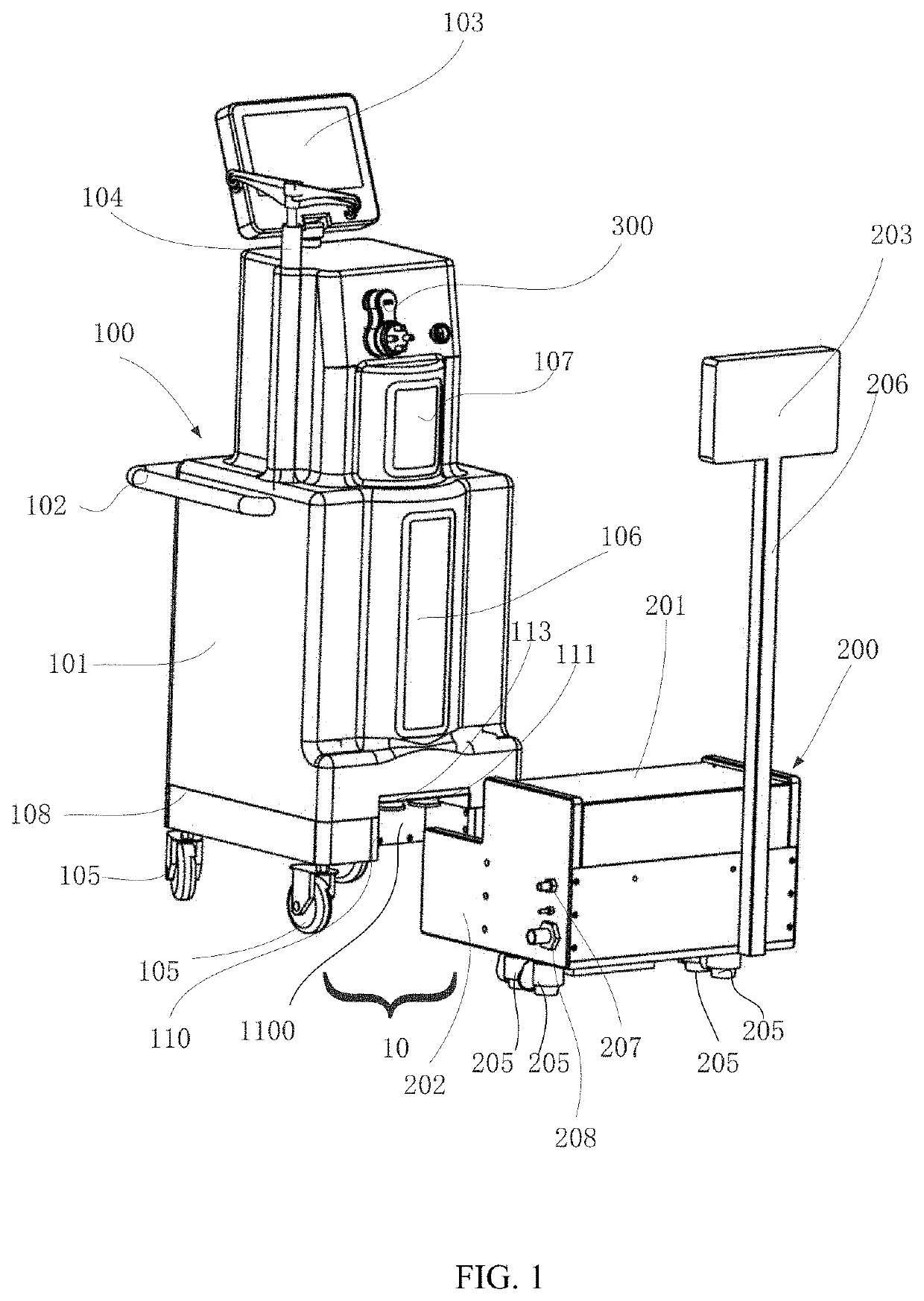
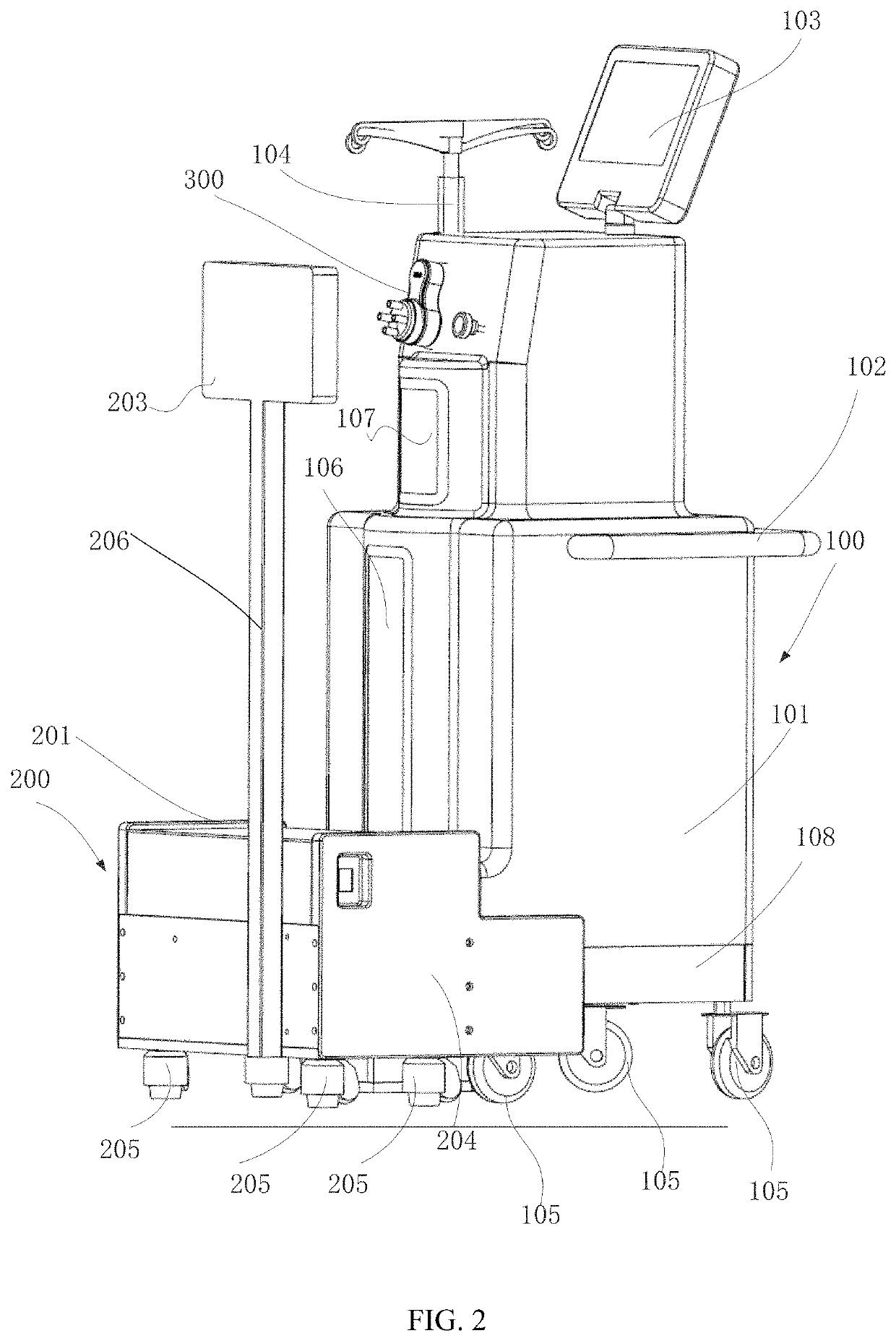
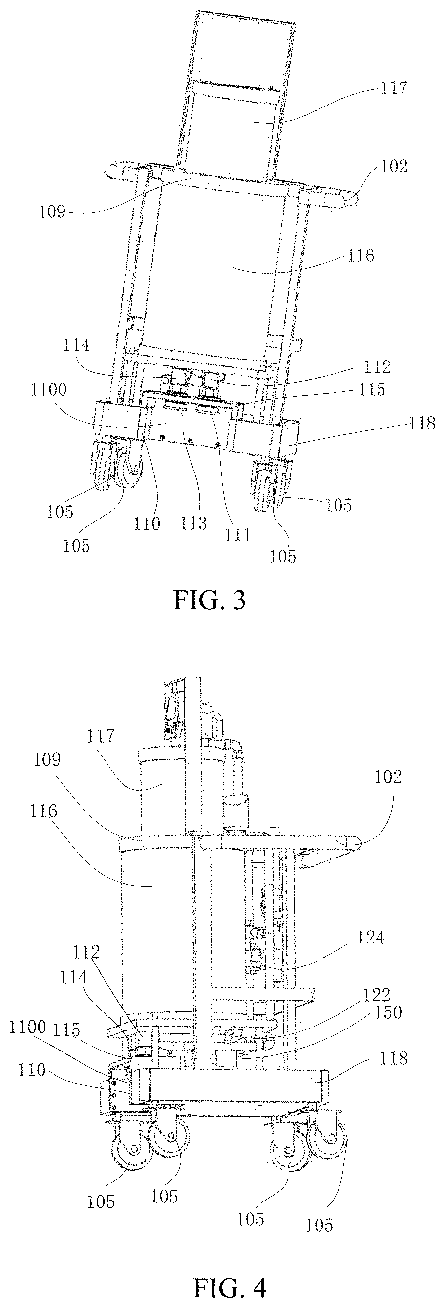
[0072]As shown in FIGS. 1 to 4, FIGS. 1 and 2 show a waste collection and disposal system 10, which includes a waste collection device 100 and a docking device 200. FIG. 1 shows the waste collection an...


PUM


Abstract

A waste collection device and a docking device are provided for collecting waste generated in a medical process. The waste collection device is docked with the docking device to discharge the waste. The waste collection device comprises a portable cart; at least one waste collection container mounted to the portable cart and configured to store waste generated in a medical process; a mating bracket mounted to the portable cart and configured to mate with the docking device; two collection end connectors attached to the mating bracket and connected to the at least one waste collection container; and two floating sleeve heads mounted to the mating bracket and correspondingly sleeved on the two collection end connectors. The floating sleeve heads can guide docking end connectors to connect with the corresponding collection end connectors so that said connectors are accurately connected, and the invention has a simple structure and low manufacture cost.

Description

CLAIM OF PRIORITY[0001]This application claims the benefit of priority from Chinese Patent Application with Application No. 201910119988.6, filed on Jun. 24, 2019 at China National Intellectual Property Administration, entitled “WASTE COLLECTION DEVICE AND WASTE COLLECTION AND DISPOSAL SYSTEM”, and from Chinese Patent Application with Application No. 201910119989.0, filed on Jun. 24, 2019 at China National Intellectual Property Administration, entitled “DOCKING DEVICE”, which are incorporated by reference herein in their entirety.TECHNICAL FIELD[0002]The invention relates to a waste collection device, a docking device, and a waste collection and disposal system, which are used to collect and process waste materials generated during a medical procedure, and to a docking device for docking with a waste collection device in a waste collection and disposal system for collection and treatment of waste materials generated during a medical procedure.BACKGROUND[0003]Waste in a liquid, semi-...

Claims


Application Information

Patent Timeline
Patent Type & Authority Applications(United States)
IPC IPC(8): A61B50/13F16L27/08B08B3/04
CPCA61B50/13B08B3/04F16L27/0804A61M2209/086A61M1/63A61M2209/10
Inventor LIANG, HONGQILEE, RICHARD YA
Owner AMSINO MEDICAL (SHANGHAI) CO LTD
Why Eureka
Try Eureka