Welding purge dam for high air flow environment

a high-air flow environment and welding technology, applied in the field ofinert gas welding, can solve the problems of difficult removal, mixed success in practice, and inapplicability of water-degradable purge dams

Active Publication Date: 2013-12-31
AQUASOL CORP LLC
View PDF41 Cites 18 Cited by
  • Summary
  • Abstract
  • Description
  • Claims
  • Application Information

AI Technical Summary

Benefits of technology

[0009]A water-degradable welding purge dam apparatus for purging a weld zone of a pipe assembly comprising first and second pipes having respective first and second ends to be welded together at a root gap. A first purge dam subassembly has a hollow first conduit defining a first air flow pathway therethrough, and has one or more air flow blocking plates fixedly mounted on the first conduit. A second purge dam subassembly has a hollow second conduit defining a second air flow pathway therethrough, and has one or more air flow blocking plates fixedly mounted on the second conduit. A hollow third conduit, defining a third air flow pathway therethrough, is interconnectable to the first and second conduits members. The purge dam apparatus is installable in the pipe assembly such that (1) the first purge dam subassembly is arranged ins

Problems solved by technology

However, there are high air flow environments in which conventional water degradable purge dams are not practical because the purge dams cannot withstand the air pressure fluctuations within the pipe

Method used


Image

  • Welding purge dam for high air flow environment
  • Welding purge dam for high air flow environment
  • Welding purge dam for high air flow environment

Examples


Embodiment Construction

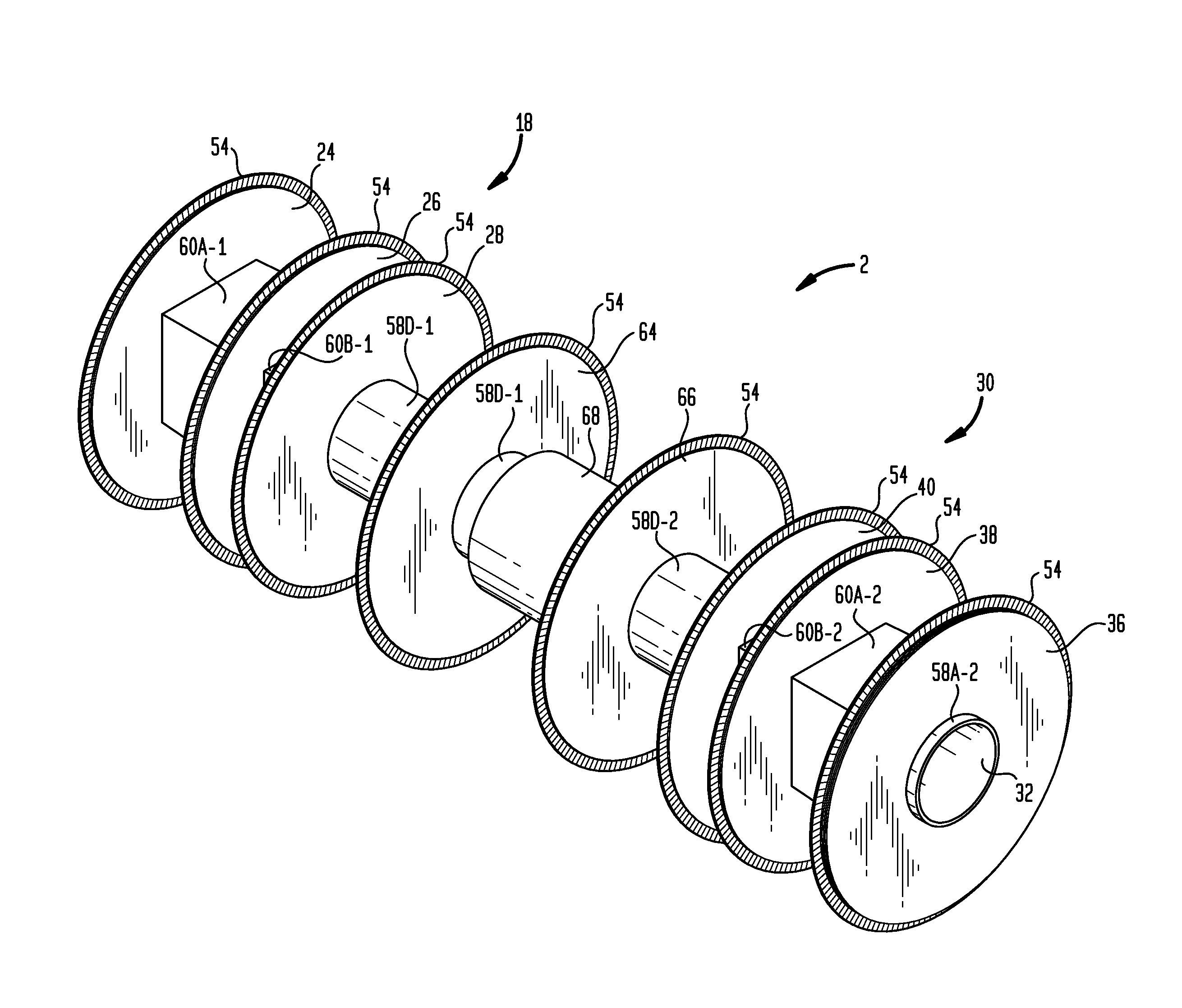
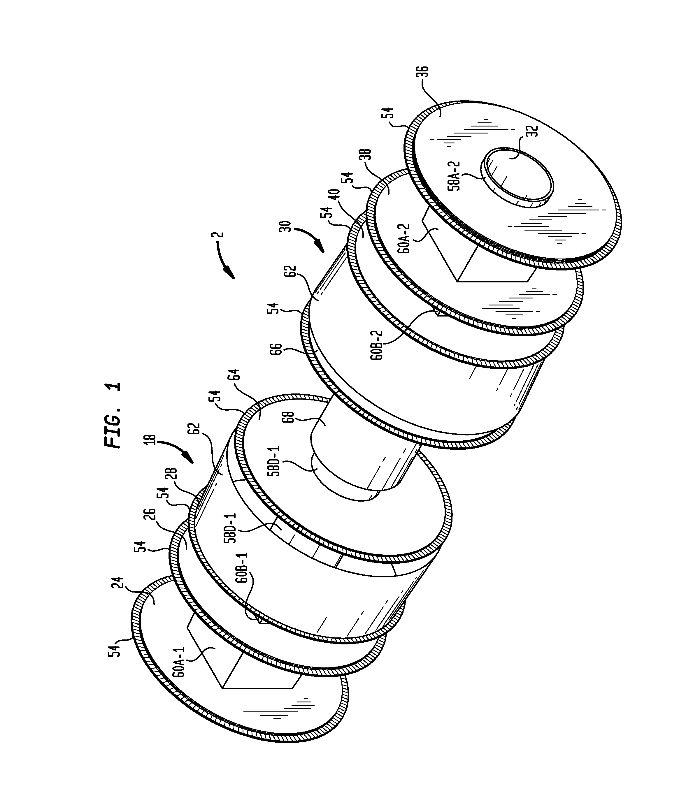
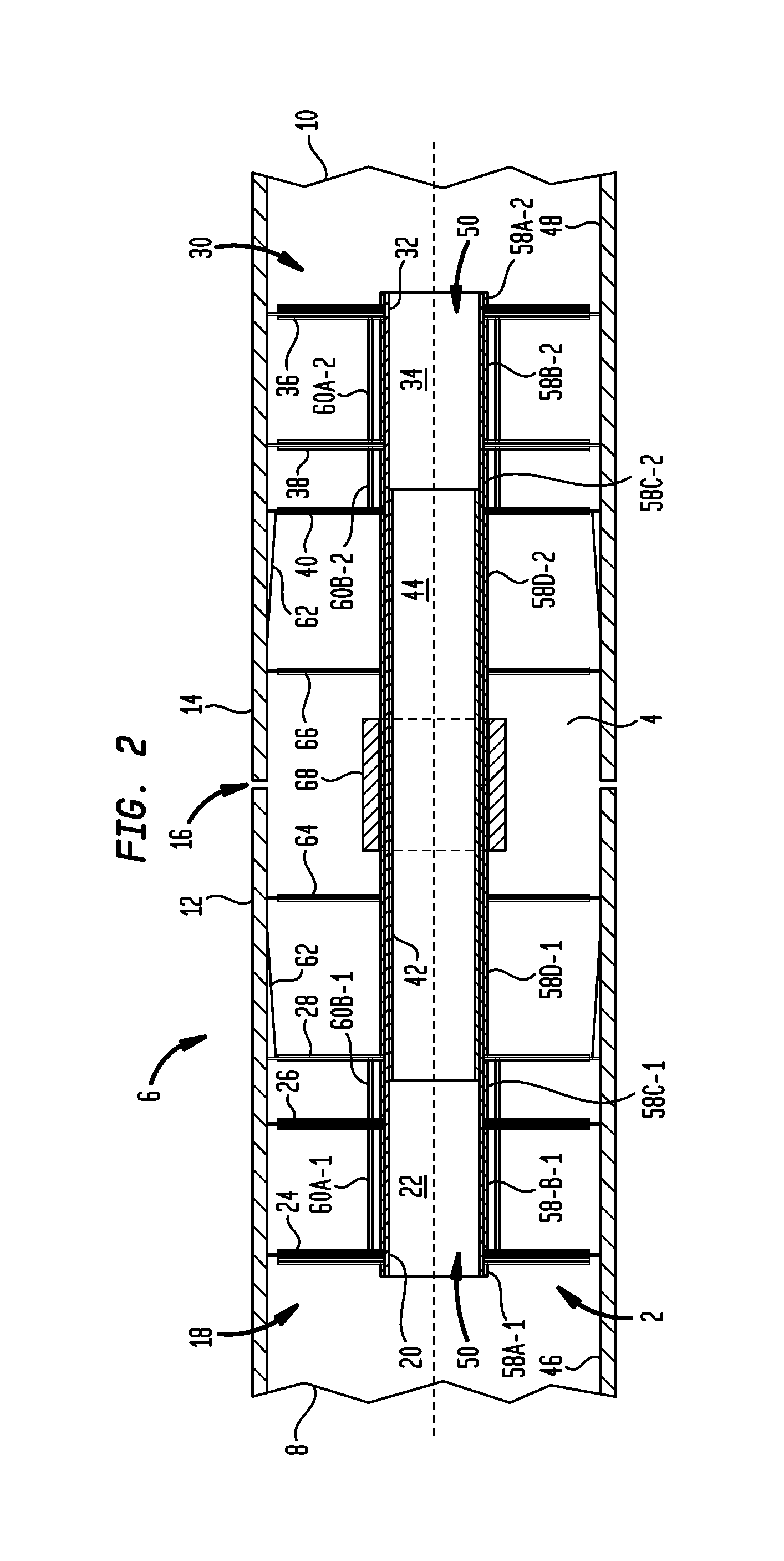
[0030]Turning now to the drawing figures, which are not necessarily to scale, like reference numbers are used to represent like elements in all of the several views. FIGS. 1 and 2 illustrate an example water-degradable purge dam apparatus 2 representing one possible embodiment of the disclosed subject matter. As best shown in FIG. 2, the purge dam apparatus 2 is adapted for purging a weld zone 4 of a pipe assembly 6 comprising a first left-side pipe 8 and second right-side pipe 10. The first and second pipes 8 and 10 have respective first and second pipe ends 12 and 14 to be butt-welded together at a root gap 16. All structural components of the purge dam apparatus 2 are made from water degradable materials. A variety of water degradable materials may be used. However, the water degradable materials will be preferably designed to (1) provide low (or zero) air permeability for critical welding applications, (2) provide sufficient strength to withstand both purge gas pressure and bidi...


PUM

PropertyMeasurementUnit
Flow rateaaaaaaaaaa
Flexibilityaaaaaaaaaa
Biodegradabilityaaaaaaaaaa

Abstract

A water-degradable purge dam apparatus for purging a weld zone of a pipe assembly comprising first and second pipes having respective first and second ends. A first purge dam subassembly adapted for installation in the first pipe end has a hollow first conduit defining a first air flow pathway. A second purge dam subassembly adapted for installation in the second pipe end has a hollow second conduit defining a second air flow pathway. Each subassembly has one or more air flow blocking plates. A hollow third conduit, defining a third air flow pathway, is interconnectable to the first and second conduits members to span the weld zone. The first, second and third air flow pathways allow pressurized air within the pipes to pass through the purge dam apparatus and the weld zone in a sequestered by-pass zone defined by the first, second and third conduits.

Description

BACKGROUND[0001]1. Field[0002]The present disclosure relates generally to inert gas welding. More particularly, the invention is directed to purge dams for retaining purge gas around a weld zone.[0003]2. Description of the Prior Art[0004]By way of background, inert gas welding is a species of arc welding in which the molten weld pool is shielded from atmospheric contamination and oxidation by bathing it with an inert gas, such as Argon, or a mixture of Helium and Argon. Popular examples of inert gas welding include TIG (Tungsten Inert Gas) welding and MIG (Metal Inert Gas) welding.[0005]When welding together pipes and other enclosed structures using inert gas welding, it is important to purge the interior of the pipe or structure in the vicinity of the weld zone to prevent corrosion and the formation of oxides on the interior side of the weld pool. Purge dams are conventionally used for this purpose. For example, when butt-welding the ends of two pipe sections to form a consolidated...

Claims


Application Information

Patent Timeline
IPC IPC(8): B23K31/02F16L55/11B32B3/02
CPCB23K9/326B23K9/325B23K9/0061B23K9/32Y10T428/214
Inventor HACIKYAN, MICHAEL
Owner AQUASOL CORP LLC
Why Eureka
Try Eureka