
Device for measuring and analysing the colour of the outer ear and ear canal

a technology for analysing and measuring which is applied in the field of measuring and analysing the colour of the outer ear and the ear canal, can solve the problems of not having an otoscope available on the market, which incorporates any device for automatic colour measurement, etc., and achieves the effect of simple and immediate diagnosis

Active Publication Date: 2013-12-31
UNIV DO PORTO
View PDF4 Cites 16 Cited by
  • Summary
  • Abstract
  • Description
  • Claims
  • Application Information

AI Technical Summary

Benefits of technology

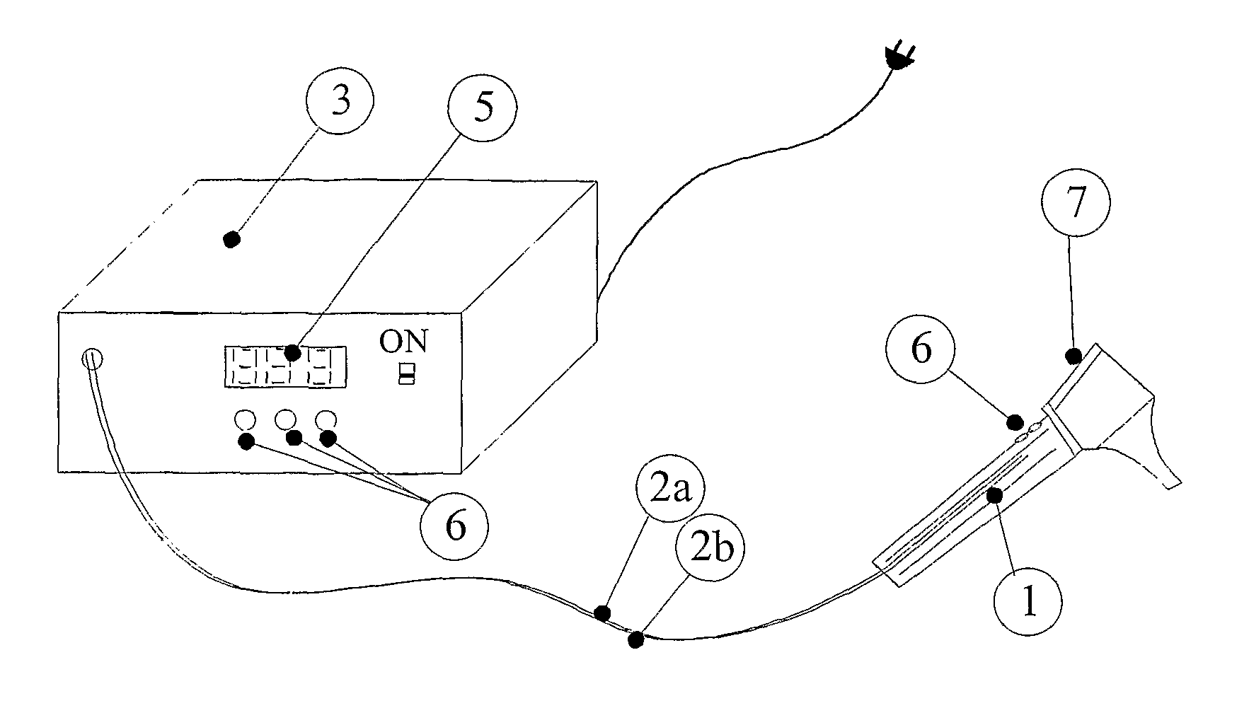
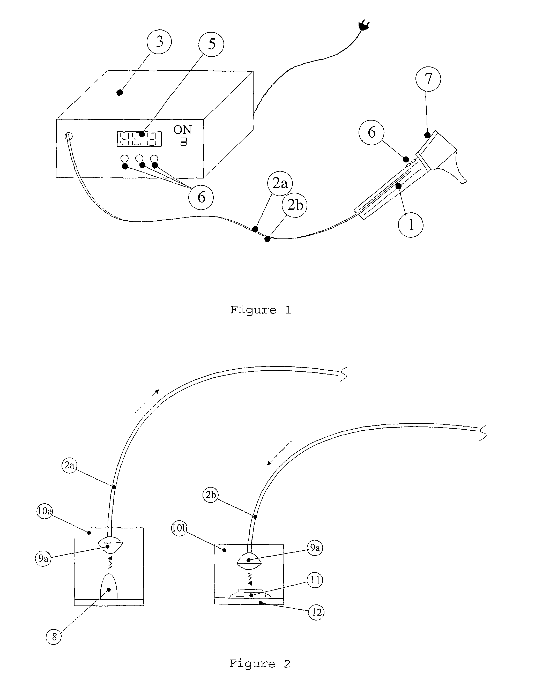
[0012]The device is essentially composed of: a standard otoscope, modified to include two optical fibers, one that illuminates the ear and another that returns the reflected light; and an electronic unit that can change linearly the power of emitted light, as well as, its colour (by combining green, blue and red intensities). The received light is also measured separately in the same three components, allowing the determination of changes in colour or texture, normally associated with ear inflammations. Command buttons placed on the otoscope handler allow the user to save the values of the three colour components. The combined value of components is shown in the digital display of the electronic unit, as well as, by a set of LEDs of green, yellow and red colours, which provide a simple and immediate diagnosis. It allows, simultaneously, the ear direct observation through a lens applied on otoscope head and a standard white light illumination.
[0014]With the implemented solution, it is possible to get objective digital information of the colour and to processing it in order to perform the diagnostic automatically, thus helping the health professional in its decision.

Problems solved by technology

None of the otoscopes available on the market, neither revealed in previous patents, incorporates any device for automatic colour measurement.

Method used


Image

  • Device for measuring and analysing the colour of the outer ear and ear canal
  • Device for measuring and analysing the colour of the outer ear and ear canal
  • Device for measuring and analysing the colour of the outer ear and ear canal

Examples


example of application

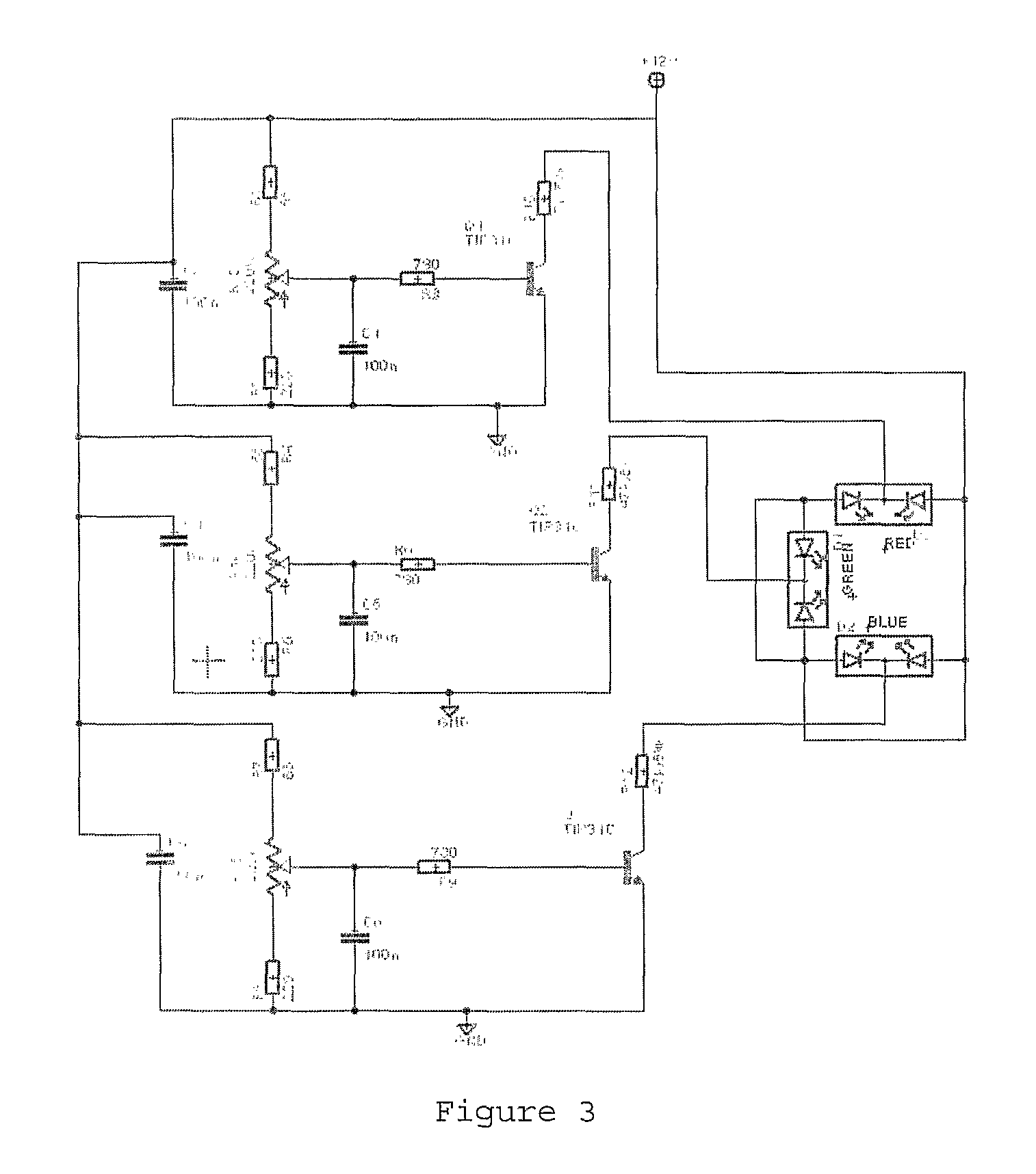
[0037]In this example, it was used the electronic circuit represented in FIG. 3 to create a light beam composed by three RGB components (red, green, blue) allowing each component strength to be changed by adjusting the corresponding potentiometer. As a tri-colour led, it was used the High Power Three Colour Led from Roithner the Lasertechnik GmbH company. The generated light beam is conducted to the otoscope by an optical fiber, being the connection of the led to the fiber made through a special lens Fibre Coupling Optic, from Roithner Lasertechnik GmbH. In this example, it was used an otoscope from the Heine company, and made two lateral holes for the insertion of the optical fibers. The reflected light is forwarded by the second fiber to the sensor SI S9032-02 photodiode, from Hamamatsu Photonics K.K. In order to facilitate its connection to the rest of the circuit it was used a mainboard Colour Sensor Evaluation Circuit—C9331 also from Hamamatsu. This board includes amplifiers fo...


PUM


Abstract

The present application concerns a device for measurement and analysis of the middle ear and ear channel color for the diagnosis of ear infections. The device is composed of a otoscope (1), including two optical fibers (2a and 2b): one for ear illumination and another returning the reflected light. The electronic unit (3) can change linearly the power of emitted light, as well as, its color. The received light is also independently measured, enabling the determination of changes on color and texture associated with the ear inflammations. Command buttons in the otoscope handler (4) enable the user to save the values of the three color components. The combined value of the components is shown in the digital display (5) of the electronic unit, as well as, by a set of LEDs (6) green, yellow and red that gives a diagnosis in a simple and immediate way. The otoscope allows, simultaneously, directly ear view through a magnifying glass (7) applied in the head of the otoscope, with a standard white light. This device is also useful in food industry.

Description

TECHNICAL DOMAIN[0001]The device object of this invention can be used in applications where it is useful to have evaluation of colour, particularly in human medicine areas (in particular in the support for ear inflammation diagnosis—otites), veterinarian and food industry. This device allows thus automatic patient middle ear colour measurement and intends to be an equipment to help health professionals in the diagnosis of ear infections.STATE OF THE ART[0002]Otoscopes are generically devices to aid otitis ear diagnosis. Otitis is ear inflammation that may cause an increase of temperature, accompanied by a change of colour and texture of the tympanum. For this purpose, otoscopes offer local lighting of the ear, usually of white colour, to allow users to view the interior of the ear and to perform the subsequent diagnosis, usually done by a doctor, in a subjective way.[0003]There are several publications that refer otoscopes for direct patient observation.[0004]U.S. Pat. No. 5,345,926...

Claims


Application Information

Patent Timeline
Patent Type & Authority Patents(United States)
IPC IPC(8): A61B1/227
CPCA61B5/0084A61B1/227
Inventor MAGALHAES MENDES, JOAQUIM GABRIELMATOS REIS, JORGE MANUELRIBEIRO DA SILVA TAVARES, JOAO MANUELCOSTA ALVES DE OLIVEIRA, GEORGETA MARIAJESUS SOEIRA, JOSE
Owner UNIV DO PORTO
Learn More