
High sensitivity glide sensor using frictional heating

a high-sensitivity, glide sensor technology, applied in the direction of digital signal error detection/correction, instruments, recording signal processing, etc., to achieve the effect of preventing heat in the thermal sensor layer from quickly dissipating into the slider body, accurate detection of very small asperities, and increasing the effectiveness of the sensor layer

Inactive Publication Date: 2013-12-31
WESTERN DIGITAL TECH INC
View PDF28 Cites 4 Cited by
  • Summary
  • Abstract
  • Description
  • Claims
  • Application Information

AI Technical Summary

Benefits of technology

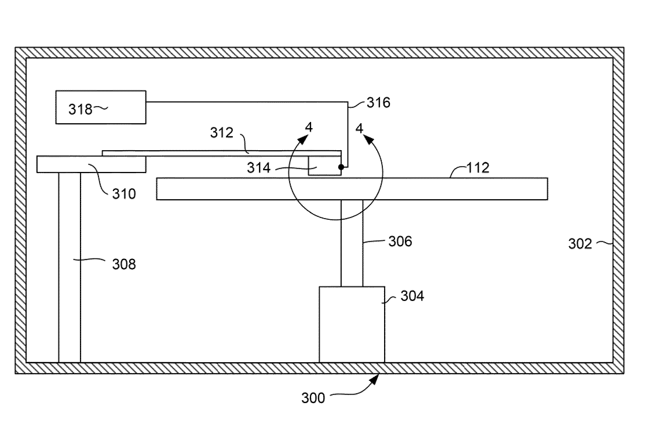
The testing device has several advantages for accurately detecting small asperities. First, the sensor is located on the air bearing surface, increasing the effectiveness of the sensor layer. Second, the thermal sensor layer is separated from the slider body by a layer of thermally insulating material, preventing heat from quickly escaping. Lastly, the thermal sensor layer can be made of a material that has a sudden change in resistance when a certain temperature is reached, increasing the sensitivity of the device.

Problems solved by technology

Secondly, the thermal sensor layer is separated from the slider body by a layer of thermally insulating material.

Method used


Image

  • High sensitivity glide sensor using frictional heating
  • High sensitivity glide sensor using frictional heating
  • High sensitivity glide sensor using frictional heating

Examples


Embodiment Construction

[0023]The following description is of the best embodiments presently contemplated for carrying out this invention. This description is made for the purpose of illustrating the general principles of this invention and is not meant to limit the inventive concepts claimed herein.

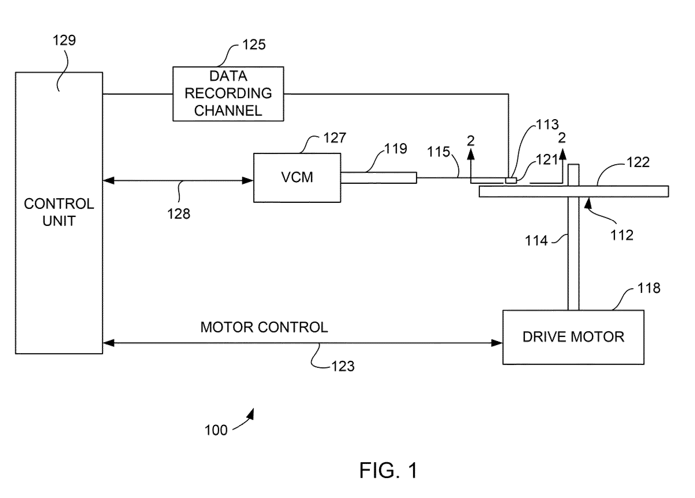
[0024]Referring now to FIG. 1, there is shown a disk drive 100 embodying this invention. As shown in FIG. 1, at least one rotatable magnetic disk 112 is supported on a spindle 114 and rotated by a disk drive motor 118. The magnetic recording on each disk is in the form of annular patterns of concentric data tracks (not shown) on the magnetic disk 112.

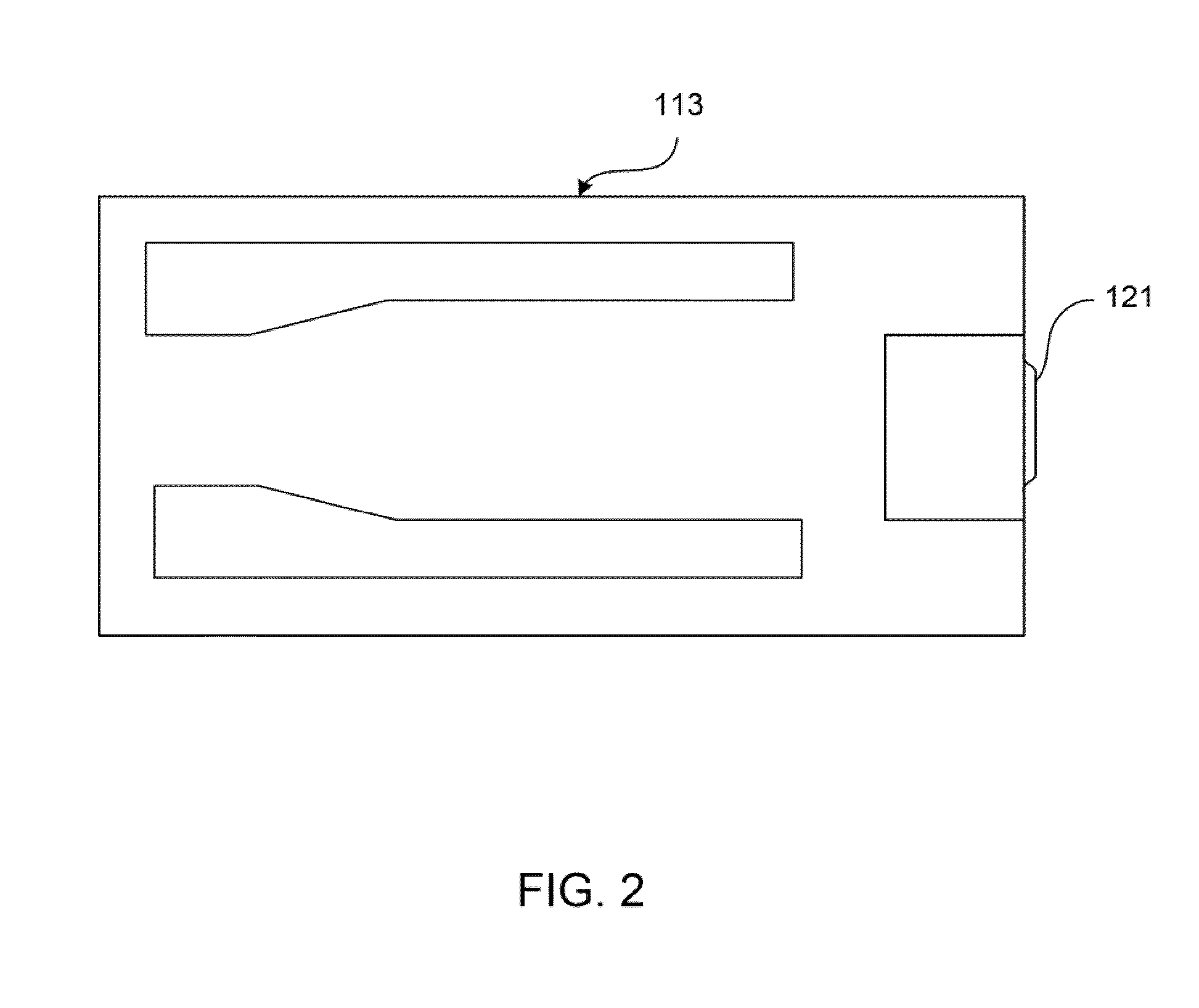
[0025]At least one slider 113 is positioned near the magnetic disk 112, each slider 113 supporting one or more magnetic head assemblies 121. As the magnetic disk rotates, slider 113 moves radially in and out over the disk surface 122 so that the magnetic head assembly 121 may access different tracks of the magnetic disk where desired data are written. Each slider 1...


PUM

PropertyMeasurementUnit
widthaaaaaaaaaa
surface thicknessaaaaaaaaaa
thicknessaaaaaaaaaa

Abstract

A tool for testing a magnetic disk for use in a magnetic disk drive. The tool detects surface defects or asperities by detecting a change in electrical resistance corresponding to a temperature change in a thermally sensitive layer. The apparatus includes a slider body having a thermally insulating layer formed on an air bearing surface of the slider body and a thermal sensor layer formed on the thermally insulating layer. The thermally insulating layer prevents thermal heat spikes in the thermal sensor layer (such as resulting from contact with an asperity) from dissipating quickly into the slider body itself. The thermal sensor layer is a material that exhibits a change in electrical resistance in response to a change in temperature and is preferably a PTC thermistor material which exhibits a large change in electrical resistance when a transition temperature has been reached.

Description

FIELD OF THE INVENTION[0001]The present invention relates to perpendicular magnetic recording and more particularly to a magnetic device for detecting defects in a magnetic media of a magnetic disk drive.BACKGROUND OF THE INVENTION[0002]The heart of a computer's long term memory is an assembly that is referred to as a magnetic disk drive. The magnetic disk drive includes a rotating magnetic disk, write and read heads that are suspended by a suspension arm adjacent to a surface of the rotating magnetic disk and an actuator that swings the suspension arm to place the read and write heads over selected circular tracks on the rotating disk. The read and write heads are directly located on a slider that has an air bearing surface (ABS). The suspension arm biases the slider toward the surface of the disk, and when the disk rotates, air adjacent to the disk moves along with the surface of the disk. The slider flies over the surface of the disk on a cushion of this moving air. When the slid...

Claims


Application Information

Patent Timeline
Patent Type & Authority Patents(United States)
IPC IPC(8): G01R33/12G11B5/33G11B27/36
CPCG11B5/40G11B2220/2516G11B20/1816G11B27/36G11B20/10203G11B5/8404
Inventor DUAN, SHANLINHE, JIZHONGHOPKINS, JOHN S.JOHNSON, KENNETH E.
Owner WESTERN DIGITAL TECH INC
Learn More