Zoom lens, optical apparatus equipped therewith, and method for manufacturing zoom lens

a technology of zoom lens and optical apparatus, applied in the field of zoom lens, can solve the problems of insufficient optical performance of conventional optical system, large size, and poor portability, and achieve the effect of reducing the body size and high optical performan

Active Publication Date: 2013-12-31
NIKON CORP
View PDF15 Cites 0 Cited by
  • Summary
  • Abstract
  • Description
  • Claims
  • Application Information

AI Technical Summary

Benefits of technology

[0004]The present invention is made in view of the above-described problems, and has an object to provide a downsized zoom lens having excellent optical performance, an optical apparatus equipped therewith and a method for manufacturing the zoom lens.
[0034]With composing a zoom lens, an optical apparatus equipped therewith, and a method for manufacturing the zoom lens in this manner, it becomes possible to obtain high optical performance with a downsized body.

Problems solved by technology

However, in an imaging device having large number of pixels, a conventional optical system cannot obtain sufficient optical performance over large photographing area, and tends to become large because of a large aperture.
As the optical system becomes large, portability becomes worse.
However, a high zoom ratio, a wider angle of view and high optical performance are very hard to compatible.
Even if they are compatible, the optical system becomes large.

Method used


Image

  • Zoom lens, optical apparatus equipped therewith, and method for manufacturing zoom lens
  • Zoom lens, optical apparatus equipped therewith, and method for manufacturing zoom lens
  • Zoom lens, optical apparatus equipped therewith, and method for manufacturing zoom lens

Examples


first embodiment

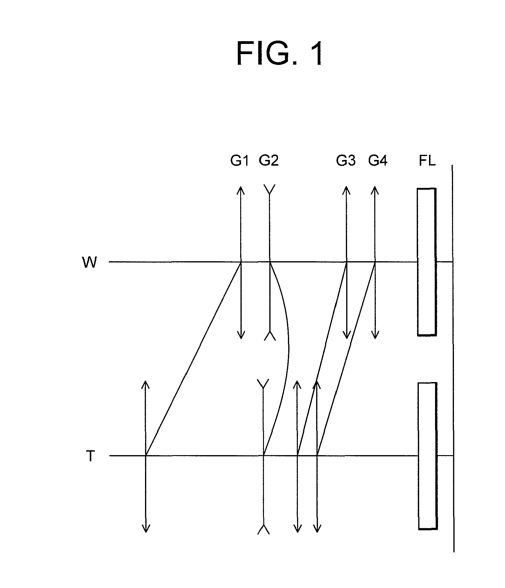
[0057]A first embodiment of the present application will be explained below with reference to accompanying drawings. As shown in FIG. 1, a zoom lens ZL is composed of, in order from an object side, a first lens group G1 having positive refractive power, a second lens group G2 having negative refractive power, a third lens group G3 having positive refractive power, and a fourth lens group G4 having positive refractive power. In the zoom lens ZL, upon zooming from a wide-angle end state, which gives the shortest focal length, to a telephoto end state, which gives the longest focal length, at least the first lens group G1 and the fourth lens group G4 are moved to the object side such that a distance between the first lens group G1 and the second lens group G2 increases, a distance between the second lens group G2 and the third lens group G3 decreases, and a distance between the third lens group G3 and the fourth lens group G4 decreases. With this configuration, the zoom lens ZL makes i...

example 1

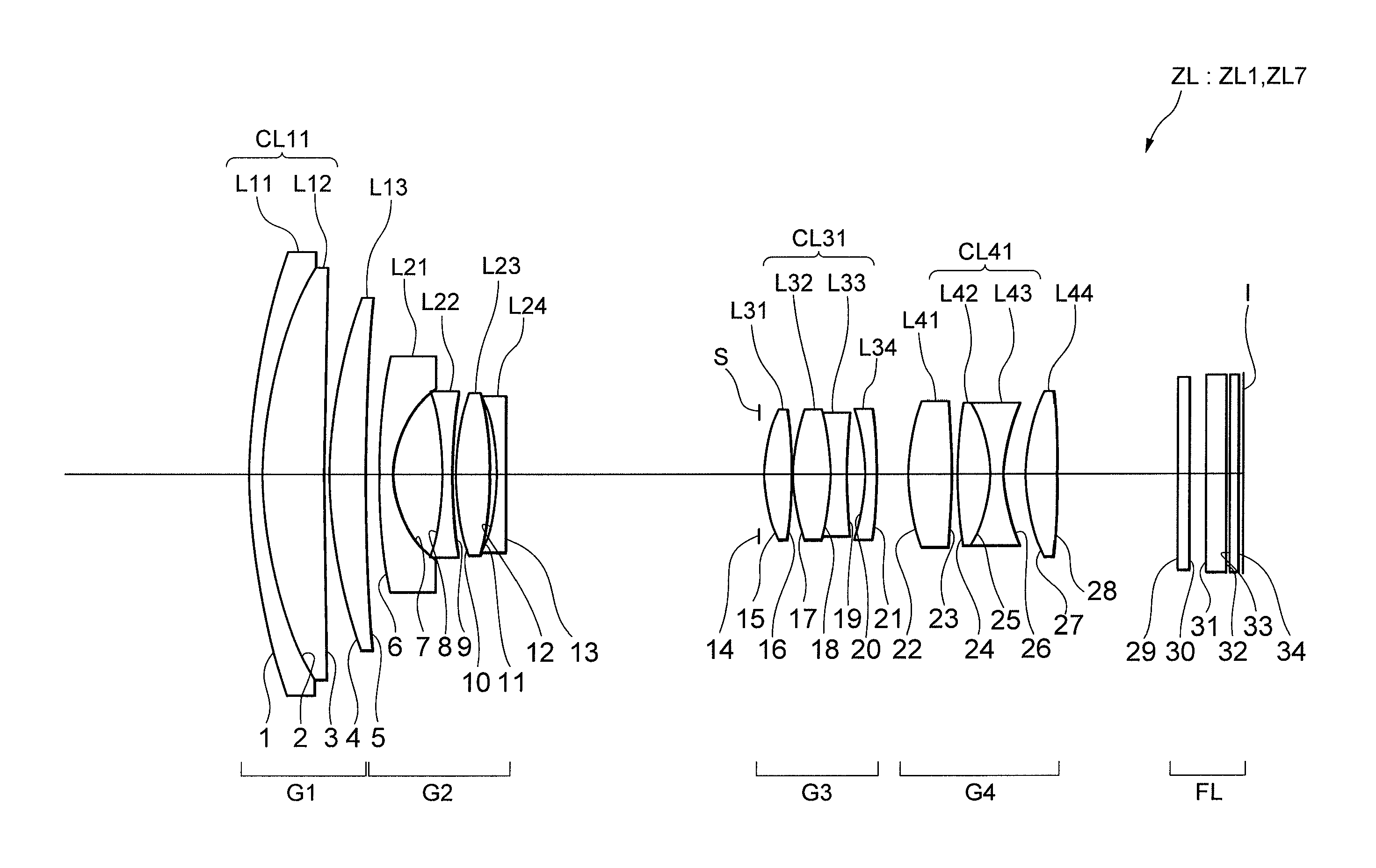
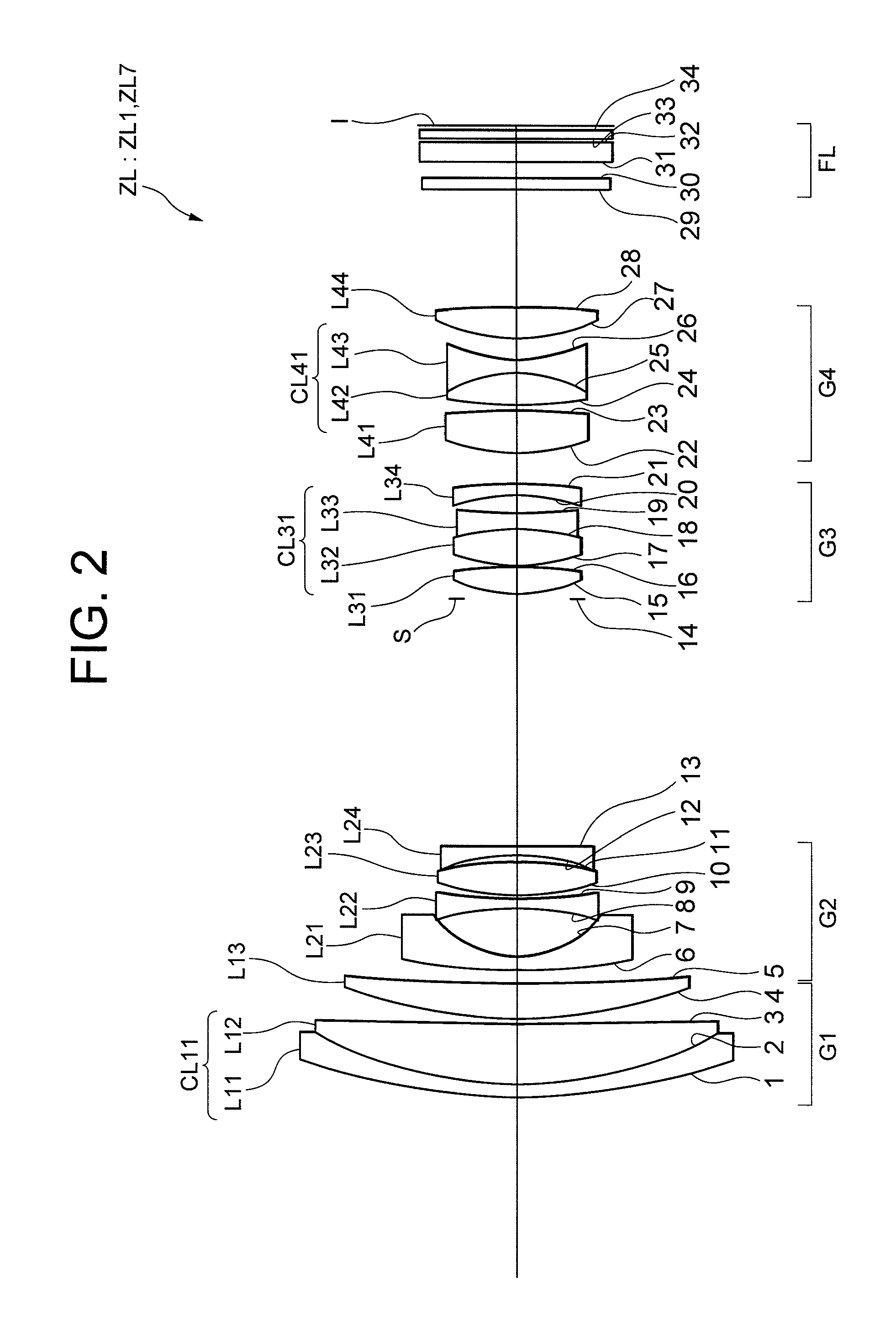
[0083]FIG. 2 is a sectional view showing a lens configuration of a zoom lens ZL1 according to Example 1 of the first embodiment. In the zoom lens ZL1 shown in FIG. 2, the first lens group G1 is composed of, in order from the object side, a cemented positive lens CL11 constructed by a negative meniscus lens L11 having a convex surface facing the object side cemented with a positive meniscus lens L12 having a concave surface facing the image side, and a positive meniscus lens L13 having a convex surface facing the object side. The second lens group G2 is composed of, in order from the object side, a negative meniscus lens L21 having a convex surface facing the object side and an aspherical surface formed on the image side, a double concave lens L22, a double convex lens L23, and a negative meniscus lens L24 having a concave surface facing the object side. The third lens group G3 is composed of, in order from the object side, a double convex lens L31, a cemented negative lens CL31 cons...

example 2

[0089]FIG. 4 is a sectional view showing a lens configuration of a zoom lens ZL2 according to Example 2 of the first embodiment. In the zoom lens ZL2 according to Example 2 of the first embodiment, the first lens group G1 is composed of, in order from the object side, a cemented positive lens CL11 constructed by a negative meniscus lens L11 having a convex surface facing the object side cemented with a positive meniscus lens L12 having a concave surface facing the image side, and a positive meniscus lens L13 having a convex surface facing the object side. The second lens group G2 is composed of, in order from the object side, a negative meniscus lens L21 having a convex surface facing the object side and an aspherical surface formed on the image side, a double concave lens L22, a double convex lens L23, and a double concave lens L24. The third lens group G3 is composed of, in order from the object side, a double convex lens L31, a cemented negative lens CL31 constructed by a double ...


PUM


Abstract

A zoom lens ZL installed in an electronic still camera 1 and the like includes, in order from an object side, a first lens group G1 having positive refractive power, a second lens group G2 having negative refractive power, a third lens group G3 having positive refractive power, and a fourth lens group G4 having positive refractive power, a given conditional expressions are satisfied, where r3F denotes a radius of curvature of an image side lens surface of the cemented lens in the third lens group, and r3R denotes a radius of curvature of an object side lens surface of the negative meniscus lens in the third lens group, thereby providing a zoom lens having excellent optical performance, an optical apparatus equipped therewith, and a method for manufacturing the zoom lens.

Description

TECHNICAL FIELD[0001]The present invention relates to a zoom lens, an optical apparatus equipped therewith and a method for manufacturing the zoom lens.BACKGROUND ART[0002]A zoom lens having a four-lens-group configuration of positive-negative-positive-positive has been known (for example, see Japanese Patent Application Laid-Open No. 1-352400). The positive-negative-positive-positive four-lens-group type zoom lens is composed of four lens groups which are, in order from an object side, a first lens group having positive refractive power, a second lens group having negative refractive power, a third lens group having positive refractive power, and a fourth lens group having positive refractive power. Upon zooming from a wide-angle end state, which gives the shortest focal length, to a telephoto end state, which gives the longest focal length, at least the first lens group and the third lens group move toward the object side. Moreover, in a digital still camera and a video camera usi...

Claims


Application Information

Patent Timeline
Patent Type & Authority Patents(United States)
IPC IPC(8): G02B15/14
CPCG02B15/173G02B15/144113
Inventor TAKE, TOSHINORI
Owner NIKON CORP
Why Eureka
Try Eureka