Floor panel

a technology for floor panels and panels, applied in the field of floor panels, can solve the problems of difficult control of tolerances in realized couplings, inability to smoothly operate embodiments, etc., and achieve the effects of precise pivoting movement, different functioning characteristics, and adequate locking

Active Publication Date: 2014-01-07
FLOORING IND LTD
View PDF46 Cites 76 Cited by
  • Summary
  • Abstract
  • Description
  • Claims
  • Application Information

AI Technical Summary

Benefits of technology

[0023]According to a second independent aspect, the invention relates to a floor panel of the above-mentioned specific type, with the characteristic that the pivotable lock-up body, opposite to the extremity forming the locking portion, comprises a support portion and that the lock-up body, between the locking portion and the support portion, in itself is free from hinge portions and bending sections. As the lock-up body is free from hinge portions and bending sections, possible influences thereof on the shape and length of the lock-up body are excluded and a fixed useful length of the lock-up body can be guaranteed, such that, amongst others, small production tolerances can be maintained, allowing precise couplings. In connection therewith, it is thus preferred that the lock-up body is performed as a rigid element.
[0054]In a preferred embodiment of the ninth aspect of the invention, the attachment portion consists of an attachment body which, viewed in cross-section, extends in a flat or rather flat direction, which means substantially in the plane of the floor panel, which attachment body is provided in a recess. Such attachment portion allows an adequate attachment, also when the invention is applied in relatively thin floor panels. Another advantage is that by somewhat altering the direction with which this attachment portion is applied in the floor panel, different functioning characteristics can be obtained and the engineer in this manner can provide for an optimization.

Problems solved by technology

However, practice has shown that this known embodiment is not always functioning smoothly and that tolerances in a realized coupling sometimes are difficult to keep under control.

Method used


Image

  • Floor panel
  • Floor panel
  • Floor panel

Examples


Embodiment Construction

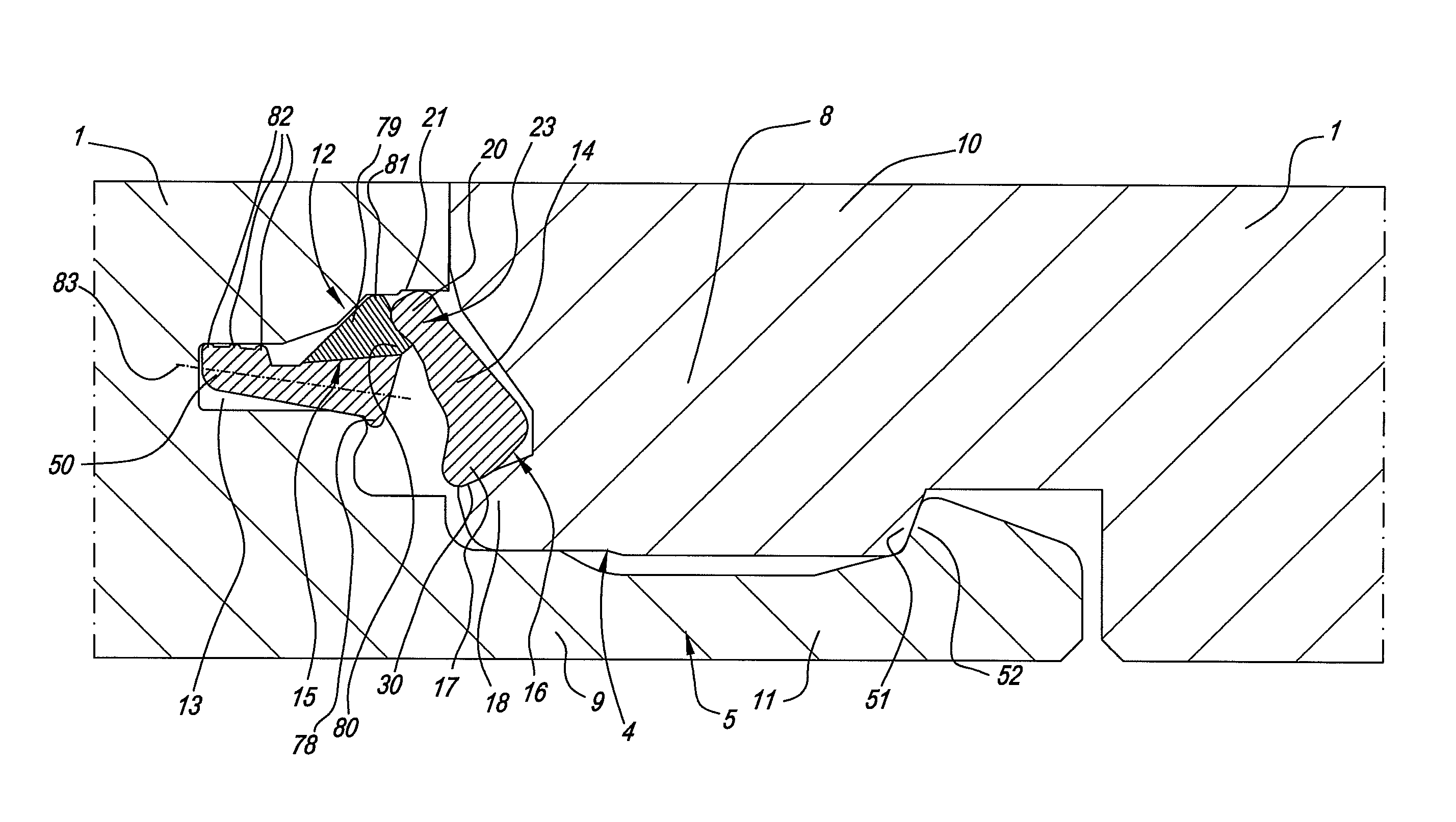
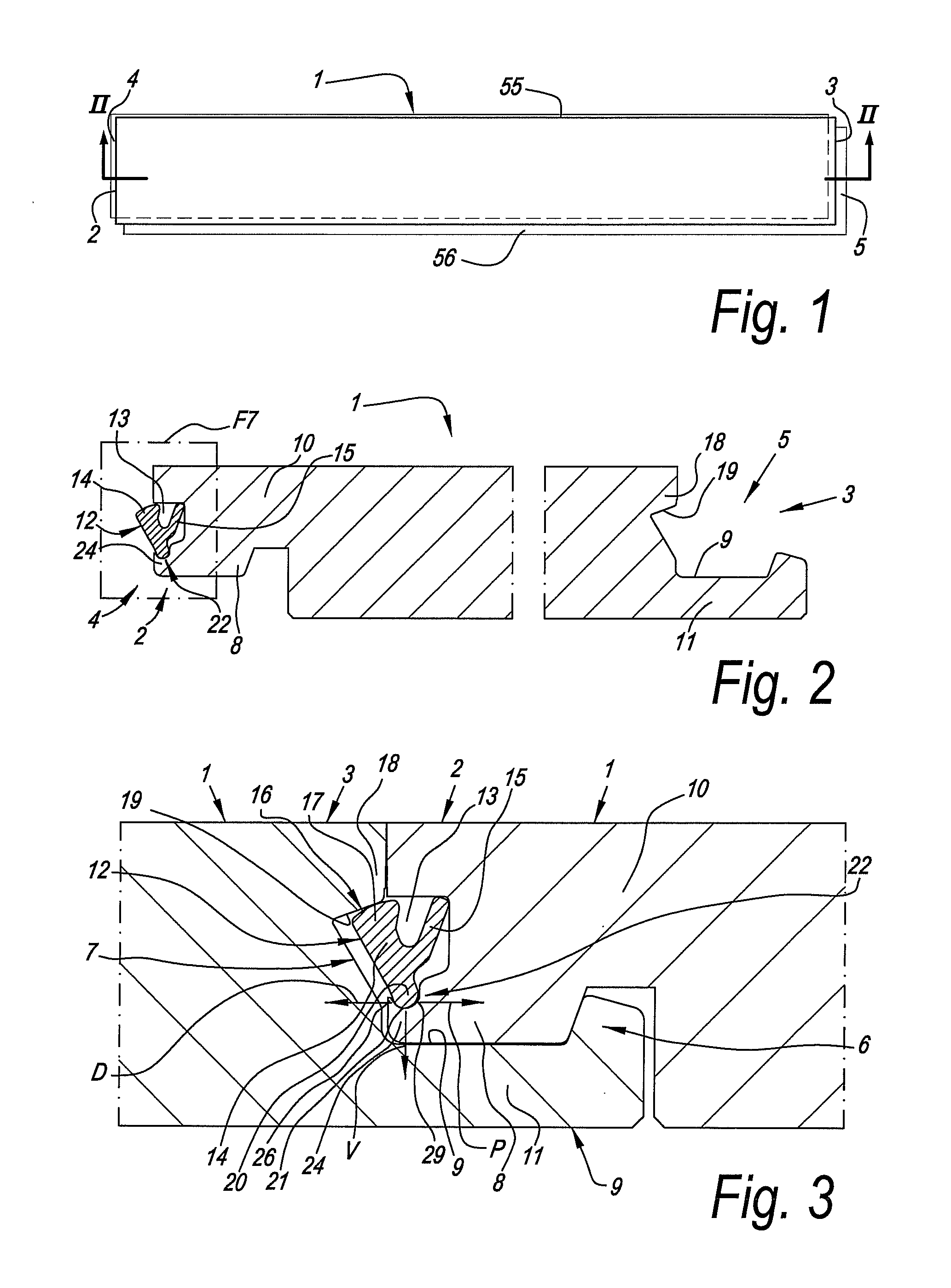
[0089]As represented in FIGS. 1 to 5, the invention relates to a floor panel 1 comprising, at least at two opposite sides 2-3, coupling parts 4-5, with which two of such floor panels 1 can be coupled to each other.

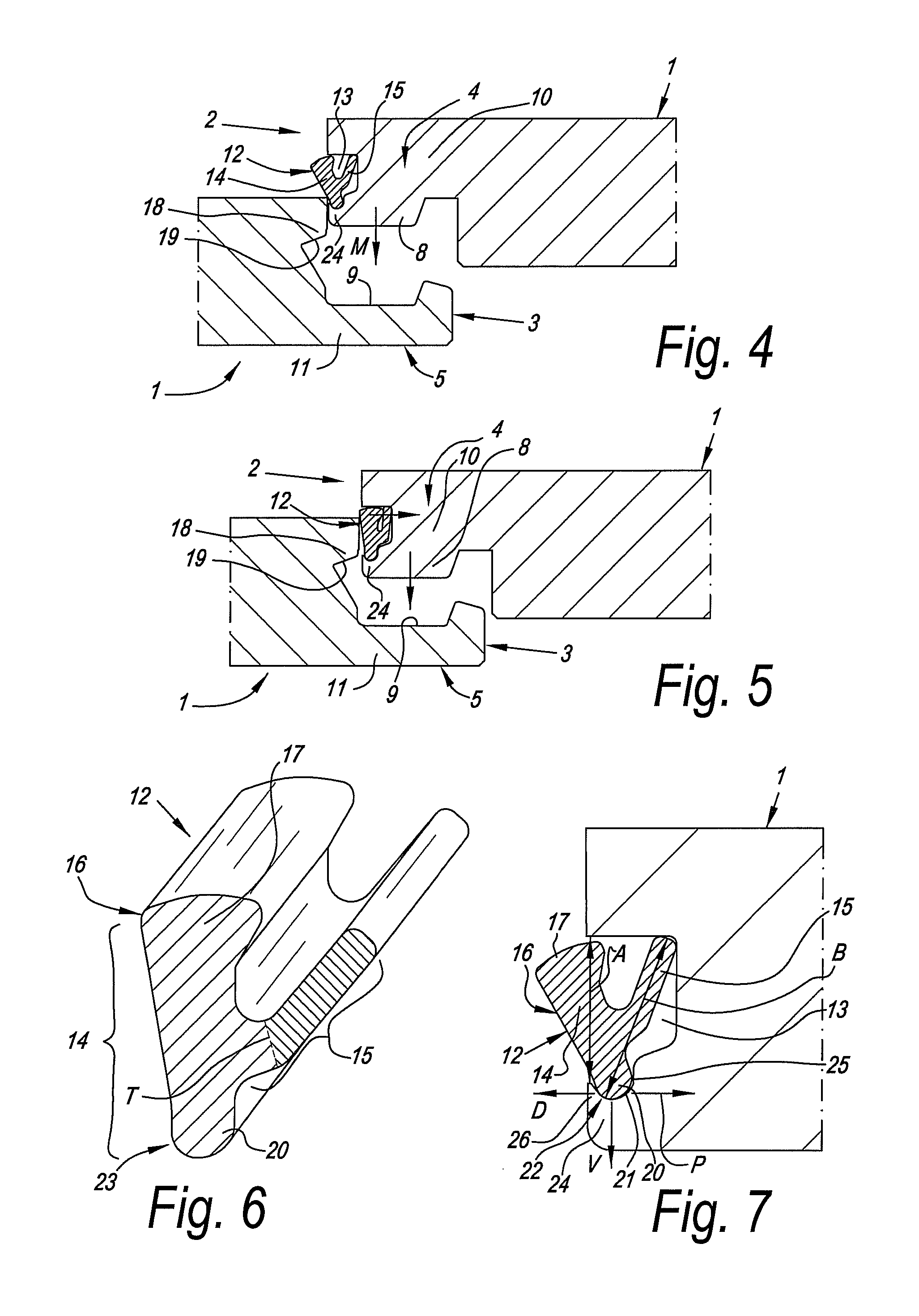
[0090]As becomes clear from the coupled condition of FIG. 3, these coupling parts 4-5 comprise a horizontally active locking system 6 and a vertically active locking system 7. The horizontally active locking system 6 comprises a male part 8 and a female part 9, which allow to connect two of such floor panels 1 to each other at the aforementioned sides 2-3 by providing one of these floor panels 1 with the pertaining male part 8, by means of a downward movement M, in the female part 9 of the other floor panel, which movement M is illustrated by means of two different positions in the FIGS. 4 and 5.

[0091]The male part 8 is formed by a downward-directed extremity of a hook-shaped part 10, whereas the female part 9 consists of a seat formed by means of an upward-directed hook-s...


PUM

PropertyMeasurementUnit
angleaaaaaaaaaa
angle A1aaaaaaaaaa
thicknessaaaaaaaaaa

Abstract

Floor panel, with a horizontally and vertically active locking system allowing that two of such floor panels can be connected to each other at said sides by providing one of these floor panels, by means of a downward movement, in the other floor panel; wherein the vertically active locking system includes a locking element in the form of an insert; wherein this locking element includes at least a pivotable lock-up body. The pivotable lock-up body includes a support portion which is rotatable against a support surface pertaining to the floor panel concerned, and more particularly in a seat.

Description

[0001]This invention claims the benefit under 35 U.S.C. 119 (e) of U.S. provisional application No. 61 / 071,201.BACKGROUND OF THE INVENTION[0002]1. Field of the Invention[0003]This invention relates to a floor panel.[0004]More particularly, it relates to a floor panel comprising coupling parts at least at two opposite sides, in the form of a male coupling part and a female coupling part, respectively, which allow to connect two of such floor panels to each other at the aforementioned sides by providing one of these floor panels with the pertaining male coupling part, by means of a downward movement, in the female coupling part of the other floor panel, such that thereby at least a locking in horizontal direction is obtained.[0005]2. Related Art[0006]Couplings allowing to couple two floor panels to each other by joining one floor panel with a downward movement into the other, in practice are subdivided into two kinds, namely a first kind wherein the coupling parts exclusively provide ...

Claims


Application Information

Patent Timeline
Patent Type & Authority Patents(United States)
IPC IPC(8): E04B2/00
CPCE04F2201/0176E04F2201/0115E04F15/02038E04F2201/0153E04F2201/0588E04F2201/0552E04F2201/049E04F15/02E04F2201/0523E04F2201/0138E04F15/045E04F15/10E04F2201/0146E04F2201/023E04F2201/043E04F2201/044E04F15/04E04F15/107
Inventor CAPPELLE, MARK
Owner FLOORING IND LTD
Why Eureka
Try Eureka