Emission control with a particulate matter sensor

a technology of particulate matter and emission control, applied in the field of emission control systems, can solve the problems of sensor reading inaccuracy, over-temperature and under-temperature conditions may still occur, etc., and achieve the effects of avoiding excess heating, saving energy, and facilitating operation

Active Publication Date: 2014-01-14
FORD GLOBAL TECH LLC
View PDF8 Cites 9 Cited by
  • Summary
  • Abstract
  • Description
  • Claims
  • Application Information

AI Technical Summary

Benefits of technology

[0004]For example, during a soot removal operation, the sensor output can provide insight into the sensor temperature, as opposed to the soot level of the engine exhaust. During sensor burn-off, the conductivity or resistivity of the sensor may change with the temperature of the sensor thus enabling the sensor to indicate whether the sensor is operating with the temperature, too high, or too low. In this way, it is possible to operate the heater more efficiently, thus avoiding excess heating that can waste energy (and thus degrade fuel economy) and / or degrade sensor performance.

Problems solved by technology

The inventors herein have recognized, however, that over-temperature and under-temperature conditions may still occur due to lack of current feedback, or other inaccuracies and variation in operating conditions.
For example, changes in exhaust flow temperature can affect sensor temperature to become too high, possibly degrading the sensor, or too low, resulting in ineffective soot removal and thus sensor reading inaccuracies.

Method used


Image

  • Emission control with a particulate matter sensor
  • Emission control with a particulate matter sensor
  • Emission control with a particulate matter sensor

Examples


Embodiment Construction

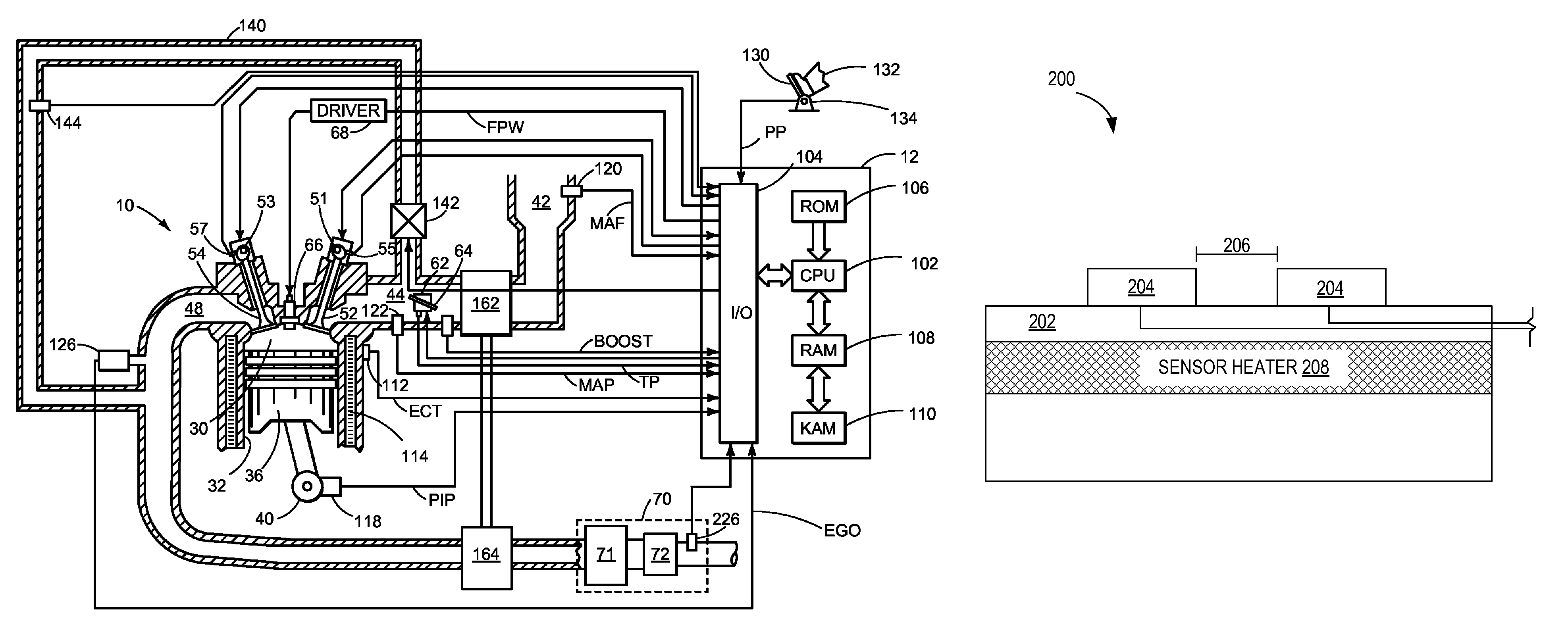
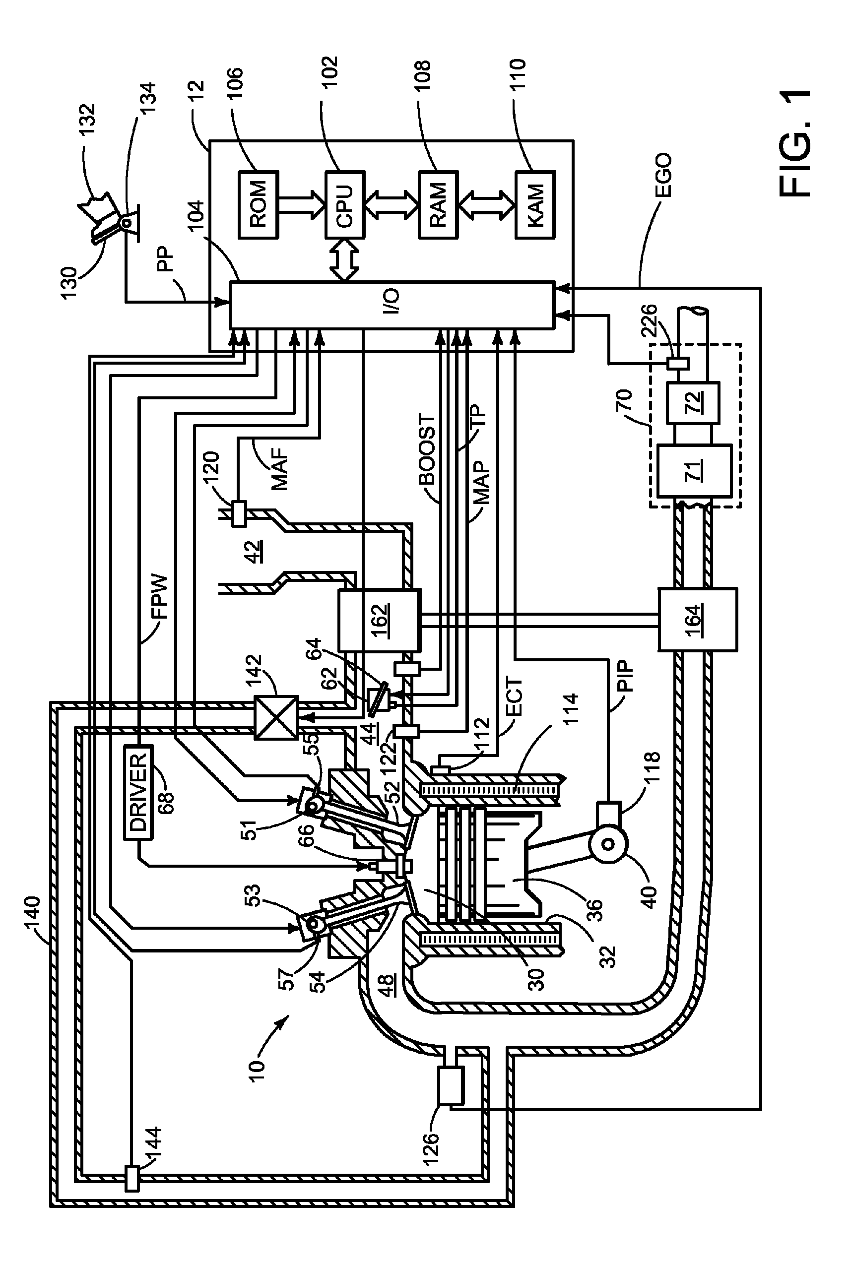
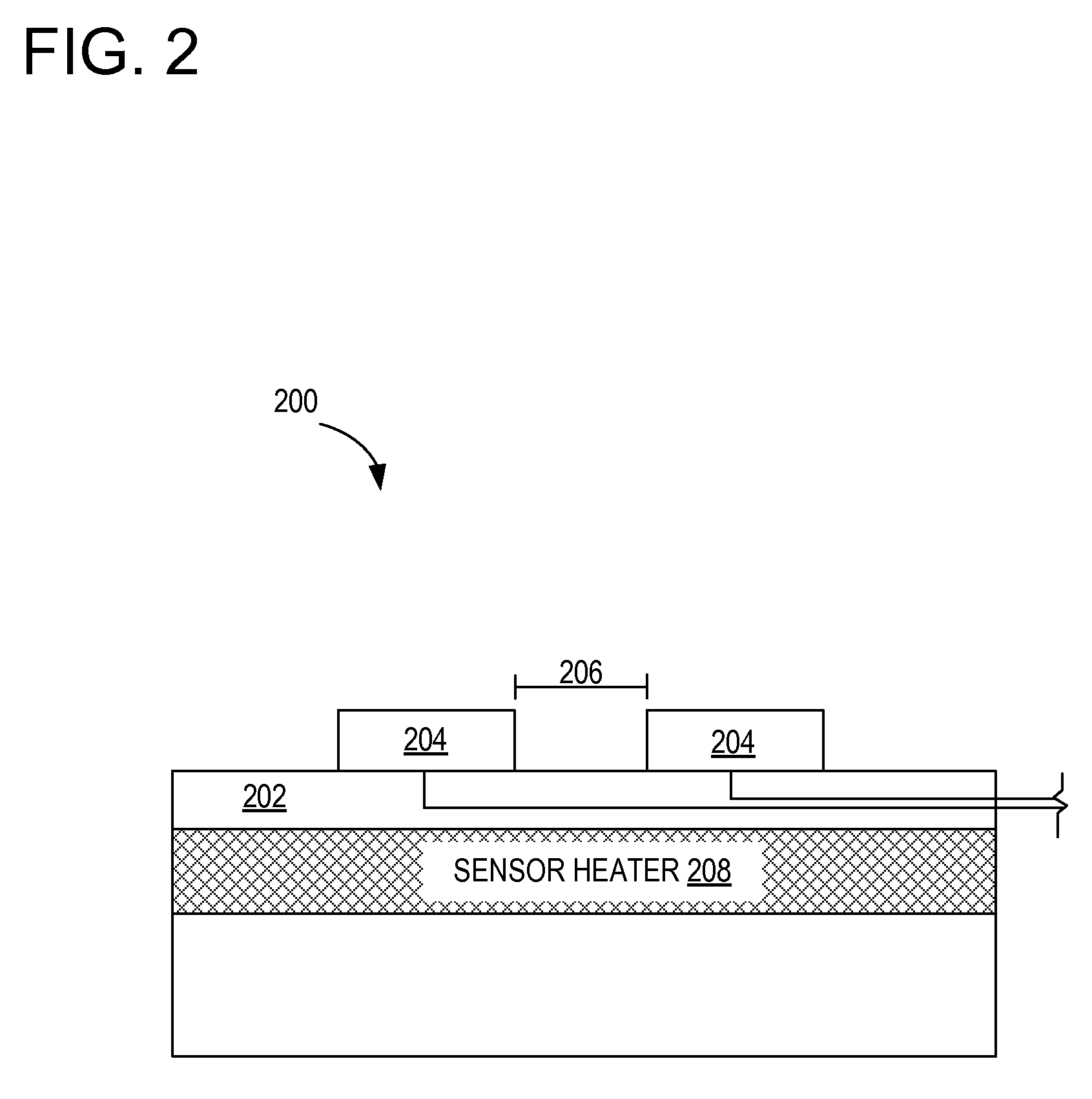
[0016]The following description relates to a particulate matter (PM) sensor regeneration system, and operation thereof. As described in more detail below, a PM sensor measures the mass or concentration of PM (soot) within an exhaust system of an internal combustion engine. Periodically, particles accumulate on a substrate of the PM sensor, and the sensor must be heated to burn off, oxidize, or otherwise drive-off the accumulated PM. In this way, the PM sensor may be regenerated by controlling the temperature of the PM sensor. During such sensor regeneration cycles, the sensor output no longer indicates soot loading in the exhaust, but rather can be used to determine whether proper regeneration conditions are being maintained. For example, the sensor output can indicate over-temperature and / or under-temperature, which can then be used to control the level of sensor heating to better maintain proper temperature control.

[0017]FIG. 1 is a schematic diagram showing one cylinder of multi-...


PUM

PropertyMeasurementUnit
conductivityaaaaaaaaaa
energyaaaaaaaaaa
massaaaaaaaaaa

Abstract

A method for controlling a particulate matter sensor heater is provided. The method includes operating the heater to burn-off soot accumulated on the sensor; and adjusting the heater level based on sensor output generated during the heater operation. In this way, improved heater control can be achieved using the sensor output already available.

Description

BACKGROUND AND SUMMARY[0001]Engine emission control systems may utilize various exhaust sensors. One example sensor may be referred to as a Particulate Matter (PM) sensor, which indicates PM mass and / or concentration in the exhaust gas. In one example, the PM sensor may operate by accumulating soot particles over time and providing an indication of the degree of accumulation as a measure of exhaust soot levels. Once full, the sensor may be regenerated by removing the stored soot at increased temperatures. The temperature may be regulated via a sensor heater, with current feedback provided to maintain proper temperatures.[0002]The inventors herein have recognized, however, that over-temperature and under-temperature conditions may still occur due to lack of current feedback, or other inaccuracies and variation in operating conditions. For example, changes in exhaust flow temperature can affect sensor temperature to become too high, possibly degrading the sensor, or too low, resulting...

Claims


Application Information

Patent Timeline
Patent Type & Authority Patents(United States)
IPC IPC(8): F01N3/02G01N7/00F01N3/00
CPCG01N27/4067F01N3/021
Inventor HOPKA, MICHAELVAN NIEUWSTADT, MICHIEL J.NOVAK, ROBERT F.
Owner FORD GLOBAL TECH LLC
Why Eureka
Try Eureka