Device for preventing slipping of vehicle

a technology for preventing slipping and vehicles, applied in the direction of non-skid devices, buckles, transportation and packaging, etc., can solve the problems of increasing accident risk, weak or handicapped users, and difficulty in quickly attaching the device to a tire, so as to prevent the catch from being loosened and prevent the vehicle from slipping

Inactive Publication Date: 2014-01-14
PARK II JUN
View PDF16 Cites 2 Cited by
  • Summary
  • Abstract
  • Description
  • Claims
  • Application Information

AI Technical Summary

Benefits of technology

[0036]In a device for preventing slipping of a vehicle according to the present invention, when a catch is locked to a clamp to attach the device to a double wheel, the catch is disposed inside a connection member, that is, the catch is disposed in a space between tires of the double wheel. Therefore, the catch locked to the clamp can be prevented from being exposed outside the tires, thus fundamentally preventing the catch from being damaged by a contact with a road surface when the vehicle travels.
[0037]Furthermore, a latch unit is provided in the clamp to which the catch is inserted and locked. Thus, the catch can be more reliably prevented from being loosened from the clamp by vibration generated by contact between the double wheel and the road surface when the vehicle travels or by tensile force that is applied to the device by the advancing force of the double wheel.
[0038]In addition, a torsion spring supports an upper surface of a locking hook of the clamp, to which the catch is locked, so as to prevent the force of locking the catch to the locking hook from being released by vibration. The latch unit also prevents the catch from being loosened from the locking hook. As such, the vehicle slipping prevention device of the present invention can more reliably prevent the catch from being loosened from the clamp in the double locking manner.
[0039]As well, the latch unit includes an elastic spring, click protrusions and a stop protrusion. Therefore, a locking knob and a latch of the latch unit can be prevented from undesirably moving upwards or downwards or rotating, and the latch unit can be maintained in a locked state or even in an unlocked state.
[0040]Moreover, a user can conveniently latch the locking hook in such a way as to rotate the locking knob at 90° using only his / her fingers. Furthermore, the vehicle slipping prevention device of the present invention resists external impact.

Problems solved by technology

On a road, such as a highway, snow chains cannot be used because they cause damage to the road and thus increase accident risk.
Meanwhile, in the case of an integrated vehicle slipping prevention device, it is difficult for a woman, weak or handicapped user to attach or detach the device to a tire of a wheel.
In addition, when a user abruptly meets a snowy or icy road, it is not easy to rapidly attach the device to a tire.
Moreover, because forward or backward movement of the vehicle is required to attach or detach the device to or from the tire, work of attaching or detaching the device to or from the tire on a sloping road is very difficult.
Thus, it is difficult to apply the integrated vehicle slipping prevention device to a large vehicle which is typically provided with double wheels.
Furthermore, in the integrated vehicle slipping prevention device, it is very inconvenient to attach or detach the chain to or from the tire.
In consideration of a relatively narrow width and small diameter of a double wheel tire used in a freight transportation vehicle, if the integrated vehicle slipping prevention device designed for passenger vehicles is attached to a tire of a truck or bus, force with which the device is attached to and is brought into contact with the tire may be unsatisfactory.
Thus, it may be impossible to effectively transmit driving force or to provide sufficient braking force.
However, this vehicle slipping prevention device has the following several problems.
Here, when braking force is continuously transmitted to the tires which rotate at a high speed, the snow chains may not be able to maintain intervals therebetween and may be focused in one direction.
Thus, braking force cannot be evenly transmitted to the entire area of the double wheel.
In addition, a load is focused on the snow chains, so that the chains are damaged or removed from the tires.
Furthermore, in the conventional vehicle slipping prevention device, when the vehicle travels, an excessive load may be focused on the device, so that coupling portions of the snow chains may be undesirably loosened, with the result that the braking force is abruptly removed and the possibility of a large accident is increased.
In other words, the conventional vehicle slipping prevention device has a problem of low safety.
When the vehicle travels on an uneven road surface, the snow chains may be undesirably gathered at one side and entangled so that the vehicle may not be steered in the direction in which the driver steers the vehicle, for example, the braking force may be applied in a direction in which the centrifugal force is applied when the vehicle suddenly turns, thus causing an accident.
Thereby, fatigue fracture may be induced.
As such, in the case where a length to which the insert end 3b of the catch 3 is exposed from the clamp 4 is increased, the conventional vehicle slipping prevention device is problematic in that the catch may be brought into contact with the road surface by centrifugal force generated when the vehicle travels, because the catch which passes through the clamp 4 is disposed outside the connection member 2.
Moreover, a broken piece of the catch 3 may be sprung out by centrifugal force, with the result that it may damage the vehicle body or tear the tires of the double wheel 200.
As well, the broken piece may strike another vehicle which is traveling on an adjacent lane.
Furthermore, in the conventional vehicle slipping prevention device, if the portion at which the catch 3 is locked to the clamp 4 is damaged, the lock of the device may be loosened.
If the loosened device is undesirably wound around the shaft of the double wheel or another wheel, a large accident may be caused.
As well, the conventional vehicle slipping prevention device is problematic in that the catch 3 which has been locked to the clamp 4 may be undesirably unlocked and removed from the clamp 4 by vibration and centrifugal force.

Method used


Image

  • Device for preventing slipping of vehicle
  • Device for preventing slipping of vehicle
  • Device for preventing slipping of vehicle

Examples


Embodiment Construction

[0057]Hereinafter, an embodiment of the present invention will be described in detail with reference to the attached drawings.

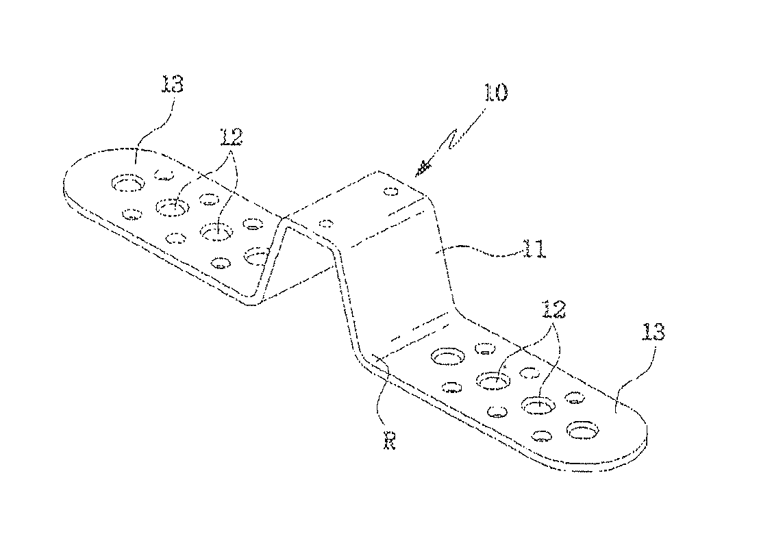
[0058]As shown in FIGS. 7 through 9, a device for preventing slipping of a vehicle according to the embodiment of the present invention includes a plurality of spikes 10 which are inserted between tires of a double wheel 200 and are in close contact with the tires, a connection member 20 which couples the spikes 10 to each other, and a fastener 50 which has a catch 30 and a clamp 40. The catch 30 is connected to a first end of the connection member 20, and the clamp 40 is connected to a second end of the connection member 20. The catch 30 is inserted into and locked to the clamp 40.

[0059]In the vehicle slipping prevention device 100 having the above construction, the number of spikes 10 is determined depending on the diameter of the tires of the double wheel 200. When the connection member 20 provided with the spikes 10 is extended in a straight line, the spi...


PUM


Abstract

A device for preventing slipping of a vehicle which includes spikes which are inserted between tires of a double wheel, a connection member which couples the spikes to each other, and a fastener which is provided on opposite ends of the connection member. The fastener includes a catch which is connected to a first end of the connection member, and a clamp which is connected to a second end of the connection member, and to which the catch is locked. When the catch is locked to the clamp to attach the device to the tires, the catch is disposed inside the connection member in a space between the tires, thus preventing the catch from coming into contact with a road surface when the vehicle travels.

Description

[0001]This application is the U.S. national phase of International Application No. PCT / KR2008 / 007415, filed 15 Dec. 2008, which designated the U.S. and claims priority to Korean Application No. 10-2007-0132401, filed 17 Dec. 2007, the entire contents of each of which are hereby incorporated by reference.TECHNICAL FIELD[0002]The present invention relates, in general, to devices for preventing slipping of vehicles and, more particularly, to a device for preventing slipping of a vehicle which is constructed such that a fastener is prevented from being brought into contact with a road surface even though tires to which device is attached are reduced in diameter attributable to abrasion of the tires, thus preventing the fastener from being damaged, and such that the fastener is prevented from being loosened or released by vibration generated when the vehicle runs or by excessive tension of a connection member coupled to the fastener, thus fundamentally preventing a damage to the vehicle ...

Claims


Application Information

Patent Timeline
Patent Type & Authority Patents(United States)
IPC IPC(8): B60C11/00
CPCB60C27/22B60C27/065B60C27/10A44B11/06Y10T152/10207
Inventor PARK, II-JUN
Owner PARK II JUN
Why Eureka
Try Eureka