
Vehicle handlebar support structure

a technology for supporting structures and motorcycles, applied in the direction of frictional rollers, steering devices, cycle equipments, etc., can solve the problems of increasing the weight of the motorcycle as a whole, complex structure, etc., and achieve the effect of reducing costs

Active Publication Date: 2014-01-14
KAWASAKI MOTORS LTD
View PDF13 Cites 9 Cited by
  • Summary
  • Abstract
  • Description
  • Claims
  • Application Information

AI Technical Summary

Benefits of technology

The present invention is designed to solve problems in existing vehicle handlebar support structures by simplifying the design and reducing the number of component parts. This simplification and lightening of the structure results in lower costs.

Problems solved by technology

It has, however, been found that the vehicle handlebar support structure disclosed in the above mentioned patent document requires the use of brackets for the support of the various gauges and, accordingly, not only does the number of component parts tend to increase, but the structure becomes also complicated, resulting in an undesirable increase of the weight of the motorcycle as a whole.

Method used


Image

  • Vehicle handlebar support structure
  • Vehicle handlebar support structure
  • Vehicle handlebar support structure

Examples


Embodiment Construction

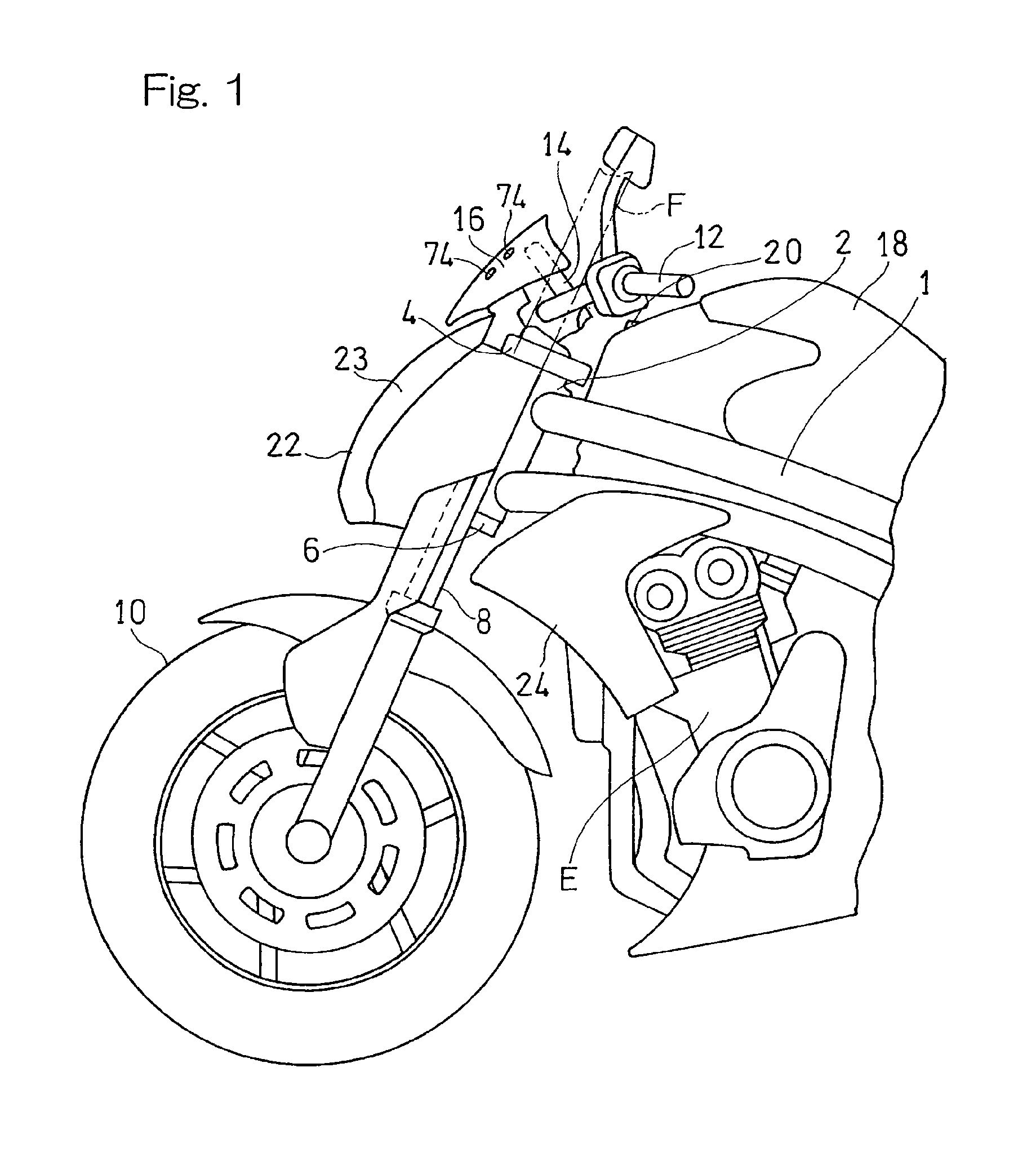
[0034]Hereinafter, a preferred embodiment of the present invention will be described in detail with reference to the accompanying drawings. FIG. 1 illustrates a front portion of a motorcycle, which is one of automotive vehicles to which the present invention is applicable, which portion is equipped with a vehicle handlebar support structure according to this embodiment of the present invention. As shown therein, a head pipe 2 is mounted on a front end portion of a main frame 1, which forms a part of a frame structure of a motorcycle; a steering shaft (not shown) is rotatably passed through the head pipe 2; and a top bridge or an upper bracket 4 and a bottom bridge or a lower bracket 6 are connected with the steering shaft. A front fork assembly including two fork tubes, which assembly is generally identified by 8, is supported by the top bridge 4 and the bottom bridge 6, and a front wheel 10 is rotatably supported by a lower end portion of the front fork assembly 8.

[0035]With the ut...


PUM


Abstract

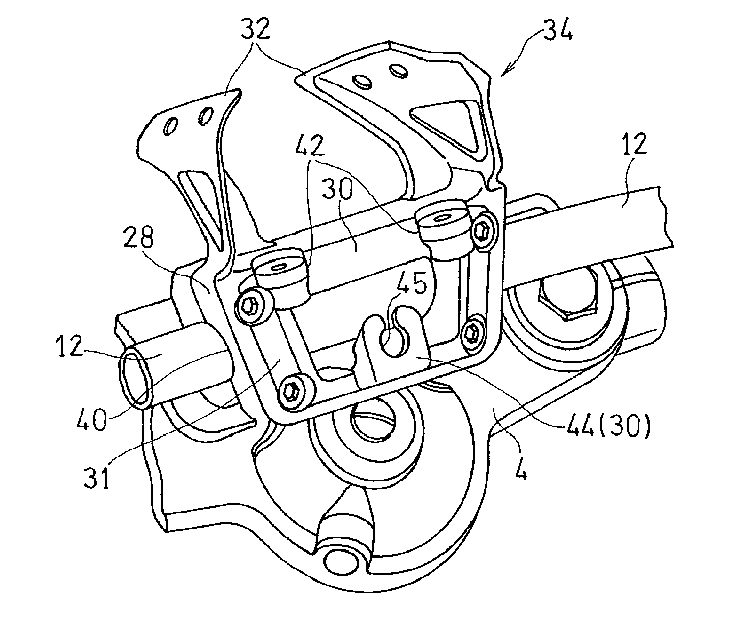
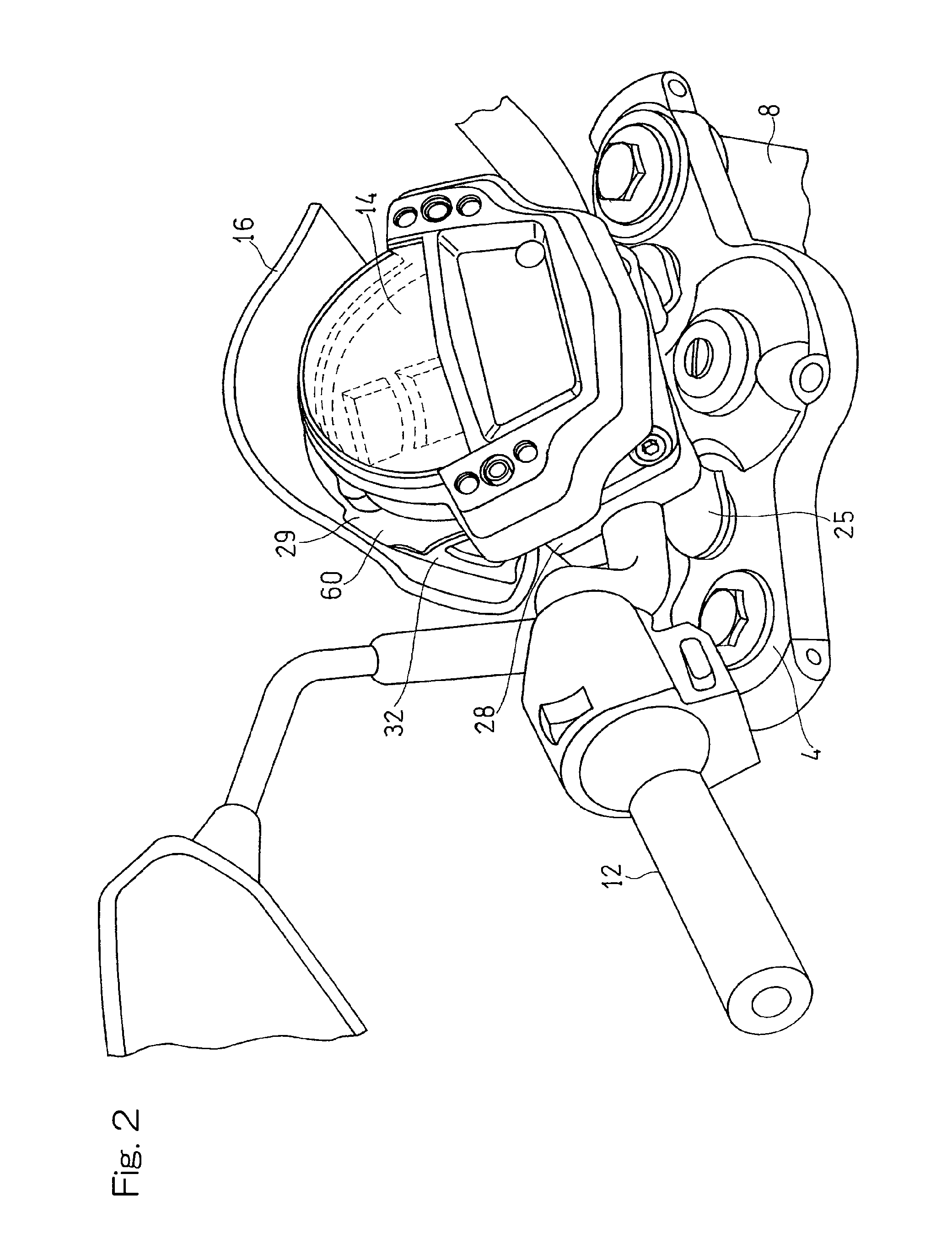
A handlebar support structure for sandwiching a steering handlebar (12) between a lower holder (25) and an upper holder (28) includes an instrument mounting area (30) for supporting an instrument panel unit (14) fitted removably thereto and a shield mounting area (32) for supporting a windshield (16) fitted removably thereto. The instrument mounting area (30) and the shield mounting area (32) are formed integrally with each other. The instrument mounting area (30) and the shield mounting area (32) altogether represent a forwardly pursed shape along a direction conforming to a forwardly tilted direction (D).

Description

CROSS REFERENCE TO THE RELATED APPLICATION[0001]This application is based on and claims Convention priority to Japanese patent application No. 2010-289523, filed Dec. 27, 2010, the entire disclosure of which is herein incorporated by reference as a part of this application.BACKGROUND OF THE INVENTION[0002]1. Field of the Invention[0003]The present invention relates to a vehicle handlebar support structure for supporting a steering handlebar in a sandwiched fashion between a lower holder and an upper holder in an automotive vehicle.[0004]2. Description of Related Art[0005]It is known that in an automotive vehicle such as, for example, a motorcycle, a lower holder is mounted on a top bridge (upper bracket) on an upper end of a front fork, and a steering handlebar is, after having been mounted on this lower holder with an upper holder mounted over the handlebar, firmly sandwiched between the lower holder and the upper holder for movement together with the front fork to thereby complete...

Claims


Application Information

Patent Timeline
Patent Type & Authority Patents(United States)
IPC IPC(8): B62K21/12B62K21/18
CPCB62J2099/0033B62J99/00B62K21/18B62J50/22B62J50/225Y10T74/2078Y10T74/20822
Inventor KAWAI, HIDEAKIKOBAYASHI, MITSURU
Owner KAWASAKI MOTORS LTD
Learn More