
Plug-in primary power connections of two modules of a gas-insulated high-voltage switchgear assembly

a high-voltage switchgear and primary power connection technology, which is applied in the direction of switchgear arrangement, high-tension/heavy-dress switch, air-break switch, etc., can solve the problems of affecting the dimensions of the gis, affecting the gis, and being relatively labor-intensiv

Active Publication Date: 2014-01-14
HITACHI ENERGY LTD
View PDF14 Cites 7 Cited by
  • Summary
  • Abstract
  • Description
  • Claims
  • Application Information

AI Technical Summary

Problems solved by technology

The assembly and dismantling of such GIS modules can be relatively labour-intensive.
When, for example, relatively high electrical powers are specified from a GIS, with the protective gas, the functional design and the materials remaining the same, this generally has a negative effect on the dimensions of the GIS, since the GIS can be implemented in a less compact form, because of the increased housing diameter.

Method used


Image

  • Plug-in primary power connections of two modules of a gas-insulated high-voltage switchgear assembly
  • Plug-in primary power connections of two modules of a gas-insulated high-voltage switchgear assembly
  • Plug-in primary power connections of two modules of a gas-insulated high-voltage switchgear assembly

Examples


first embodiment

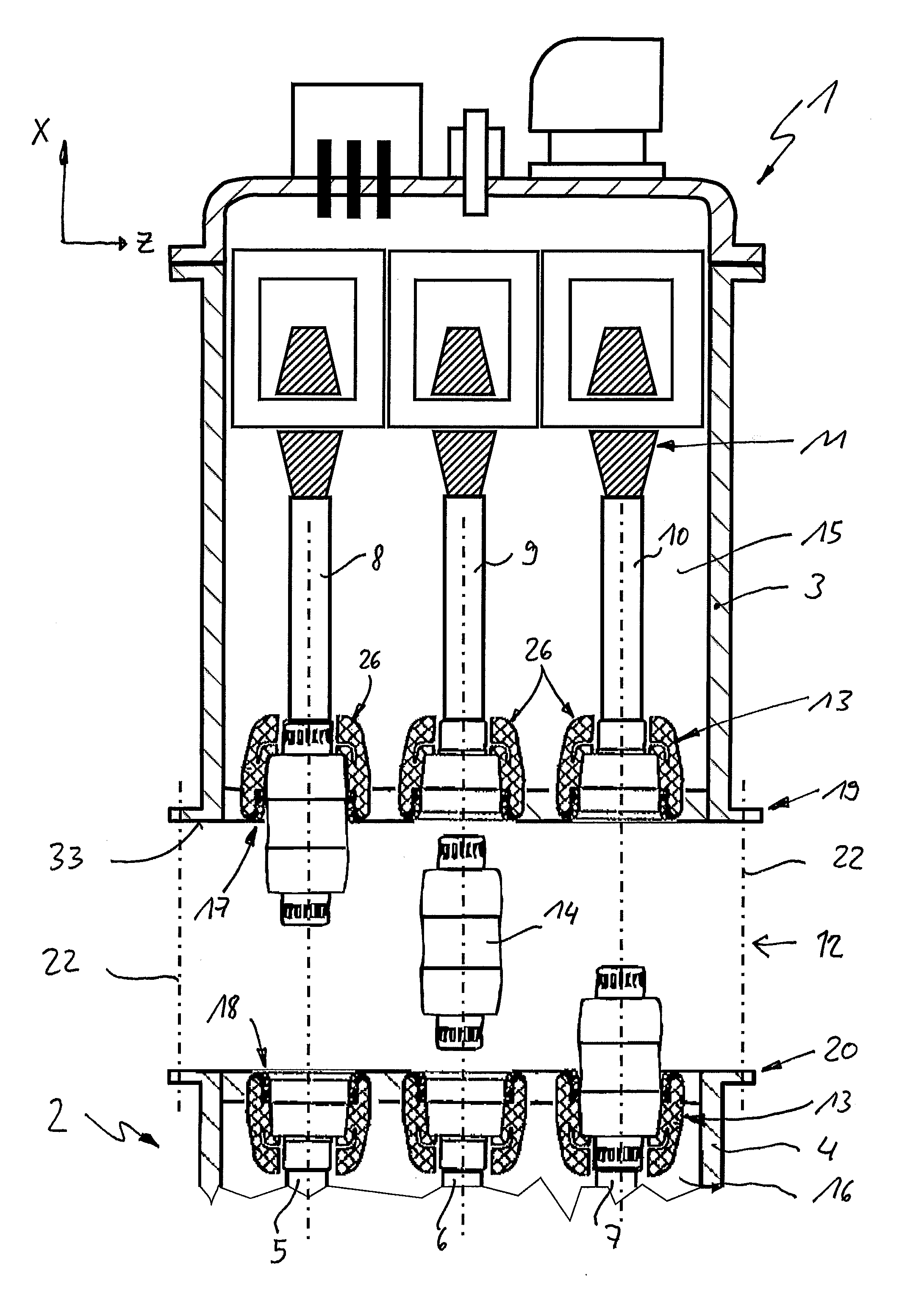
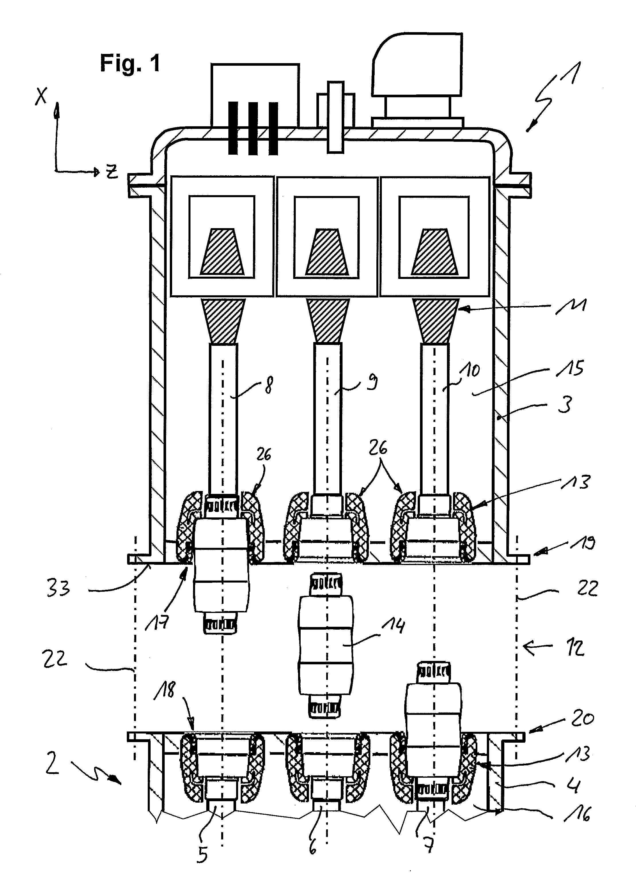
[0047]FIG. 1 shows a longitudinal section through a first two three-phase-encapsulated HV-GIS modules in the uncoupled state in accordance with an exemplary embodiment of the present disclosure. The longitudinal section through two three-phase-encapsulated HV GIS modules in the uncoupled state in FIG. 1 illustrates, for example, a first GIS module 1 which can be connected to a second module 2. The first module 1 is, for example, a voltage converter, while the second module 2, which is shown only in its connection area, represents, for example, a connection module in a gas-insulated switch panel. Both modules have a respective housing 3, 4. The housing 4 includes three nominal conductor sections (phase conductors) 5, 6, 7, which extend in the X direction. The housing 3 likewise includes three corresponding nominal conductor connections (phase conductors) 8, 9, 10, which are connected to corresponding instrument transformers 11. The phase conductors 5, 6, 7 of the first module can be ...

second embodiment

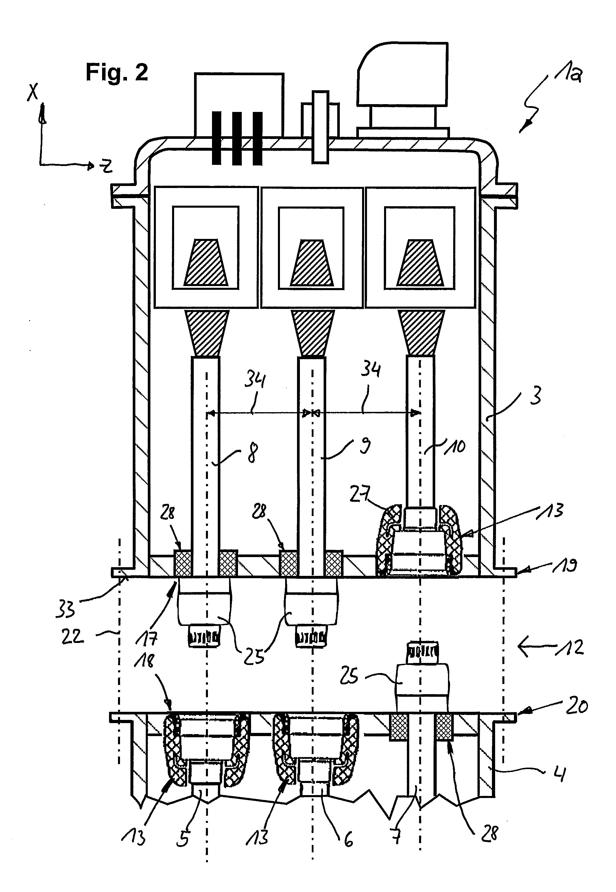
[0054]FIG. 2 shows a longitudinal section through a second two three-phase-encapsulated HV GIS modules in the uncoupled state in accordance with an exemplary embodiment of the present disclosure. FIG. 2 shows two three-phase encapsulated HV-GIS modules in the uncoupled state, in a similar manner to FIG. 1. Because of this similarity, only the differences from FIG. 1 will be described in the following text. Identical elements or elements having the same effect are provided with the same reference symbols. The flange-like adapter sections 19, 20 of the housings 3, 4 of the modules 1a, 2a once again in each case have a housing-side connecting opening 17, 18 for each phase, in the connecting area of the respective modules. Instead of the female elements 13, two phase connections of the first module, as part of the respective plug connections 12, now have a contact pin 25 as a male part, as well as a contact socket as a female contact element. In a corresponding manner, two phase connect...


PUM


Abstract

A gas-insulated switchgear assembly having a first module and a second module, which each have a gas area, which is in the form of a pressure vessel, is filled with an insulating gas and has at least two phase conductors. The first module is connected to the second module such that the first gas area and the second gas area are hydraulically separated from one another by an insulating body, while the phase conductors in the first module are electrically connected to the phase conductors at the same electrical potential in the second module. The at least two phase conductors in the first module can be electrically connected to the at least two phase conductors at the same electrical potential in the second module, in each case via a detachable plug connection.

Description

RELATED APPLICATION(S)[0001]This application claims priority as a continuation application under 35 U.S.C. §120 to PCT / EP2010 / 056610, which was filed as an International Application on May 12, 2010 designating the U.S., and which claims priority to German Application 10 2009 022 105.0 filed in Germany on May 20, 2009, and German Application 10 2009 022 127.1 filed in Germany on May 20, 2009 and German Application 10 2009 042 644.2 filed in Germany on Sep. 23, 2009 and European Application No. 10000428.2 filed in Europe on Jan. 18, 2010. The entire contents of these applications are hereby incorporated by reference in their entireties.FIELD[0002]The present disclosure relates to a switchgear assembly, such as, plug-in primary power connections of two modules of a gas-insulated high-voltage switchgear (GIS) assembly, and to an electrical connection between two primary conductors of two GIS modules which are coupled to one another and whose primary conductors for each phase are at the ...

Claims


Application Information

Patent Timeline
Patent Type & Authority Patents(United States)
IPC IPC(8): H02B13/00H02B1/20
CPCH02B13/005H02B13/0352
Inventor ZWICKY, DANIELSAXL, DAVIDSCHALBER, HORSTMANN, MICHAELKUHL, DANIEL
Owner HITACHI ENERGY LTD
Learn More