Ultrasonic water level gauge and control device

a control device and ultrasonic technology, applied in the direction of liquid/fluent solid measurement, machines/engines, instruments, etc., can solve the problems of destroying the sound path that goes through the air from the top to the water surface in the boiler by using an air-coupled transducer, and no assurance at all of the ultrasonic water level measurement to be successful in the boiler

Active Publication Date: 2014-01-14
XYLEM IP HLDG
View PDF41 Cites 6 Cited by
  • Summary
  • Abstract
  • Description
  • Claims
  • Application Information

AI Technical Summary

Benefits of technology

[0009]According to some embodiments, the ultrasonic water level gauge and control system may be configured to make the ultrasonic water level measurement and control in devices, e.g., like the boiler or the hot water tank, feasible and practical. When compared to the currently known level gauge and control techniques for a known boiler, i.e., the sight glass and the level switches, the present invention combines two important aspects of the water level measurement and the level control, in that it is an automatic and non-invasive approach without any significant requirements for the modification on the boiler itself, and it has a high and satisfactory measurement and control accuracy.
[0017]According to some embodiments, the apparatus may also take the form of a signal processor or control unit module that forms part of an ultrasonic transducing and signal processing arrangement that is configured to be coupled to a gauge coupled on the outside of a device, including a boiler or hot water tank, containing liquid therein, where the gauge is configured to contain a small part of the liquid of the device. The signal processor or control unit module may comprise at least one processor and at least one memory including computer program code, the at least one memory and computer program code configured, with the at least one processor, to cause the apparatus at least to: reflect an ultrasonic pulse off a liquid surface of the small part of the liquid of the device contained in the gauge, and determine the level of liquid in the device based at least partly on the ultrasonic pulse reflected off the liquid surface of the small part of the liquid of the device contained in the gauge, including based at least partly on a time of flight analysis related to the ultrasonic pulse reflected off the liquid surface of the small part of the liquid of the device contained in the gauge.

Problems solved by technology

Due to the harsh working conditions of high temperature, high pressure, high humidity and condensate, and turbulent water surface while boiling, most techniques including some ultrasonic level measurements for a liquid tank through either an air path approach or a water path approach might be unfeasible and impractical for this specific application.
Different from most conventional applications for ultrasonic liquid level measurements at a liquid tank, the worst scenarios for a boiler application case are steamy condensate and turbulent water surfaces while boiling, as well as high pressure and temperature.
The sound path that goes through the air from the top to the water surface in a boiler by using an air-coupled transducer will be ruined soon after the steam and condensate build up in the path when the water is boiling.
Hence, based on this understanding in the prior art, there is no assurance at all for the ultrasonic water level measurements to be successful in a boiler.

Method used


Image

  • Ultrasonic water level gauge and control device
  • Ultrasonic water level gauge and control device
  • Ultrasonic water level gauge and control device

Examples


Embodiment Construction

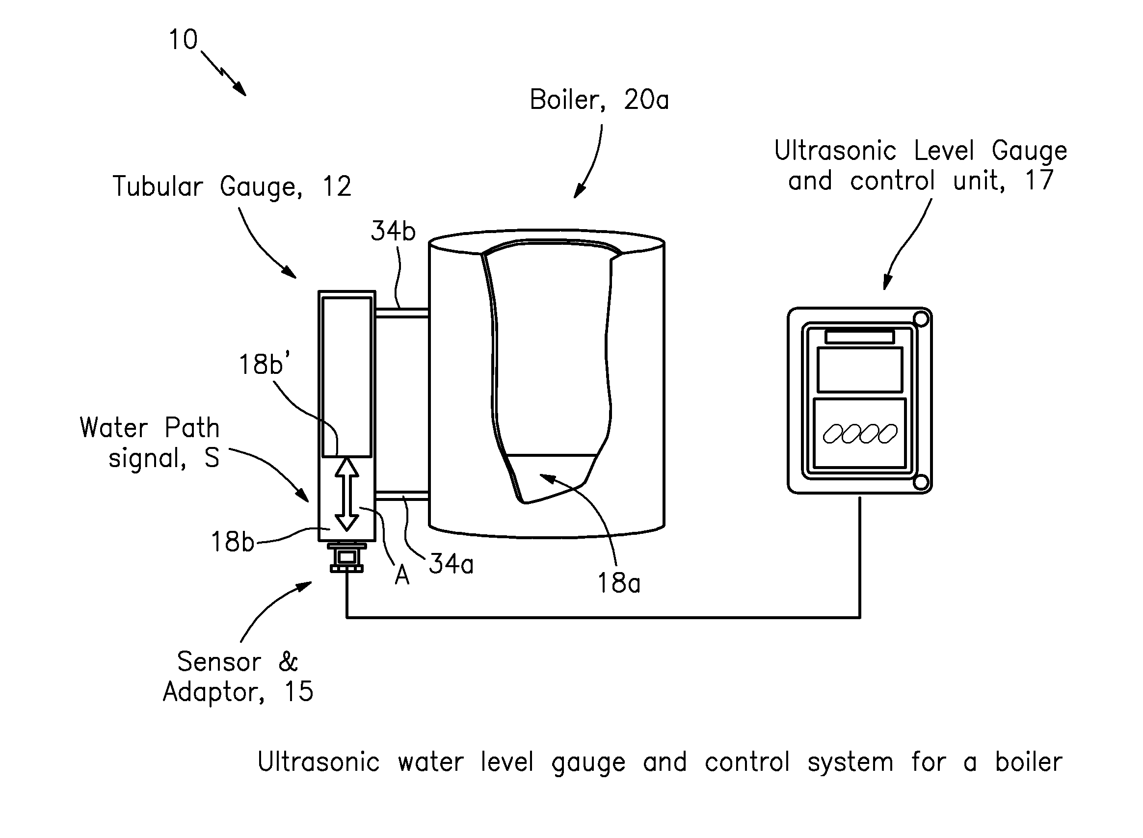
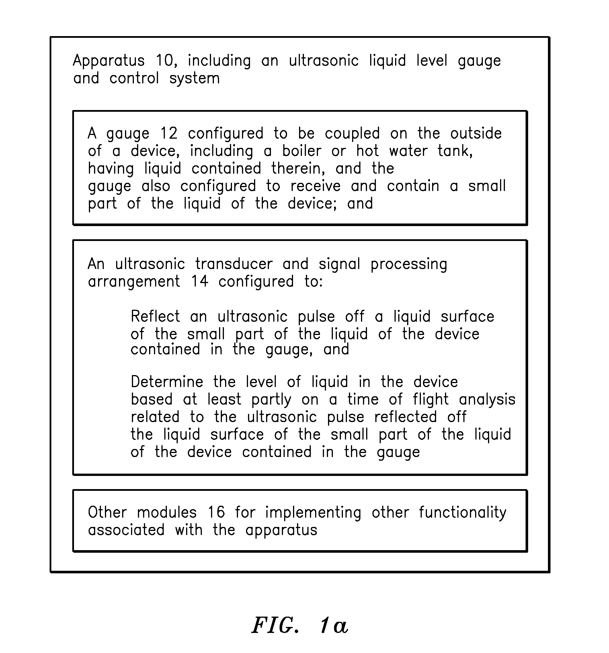
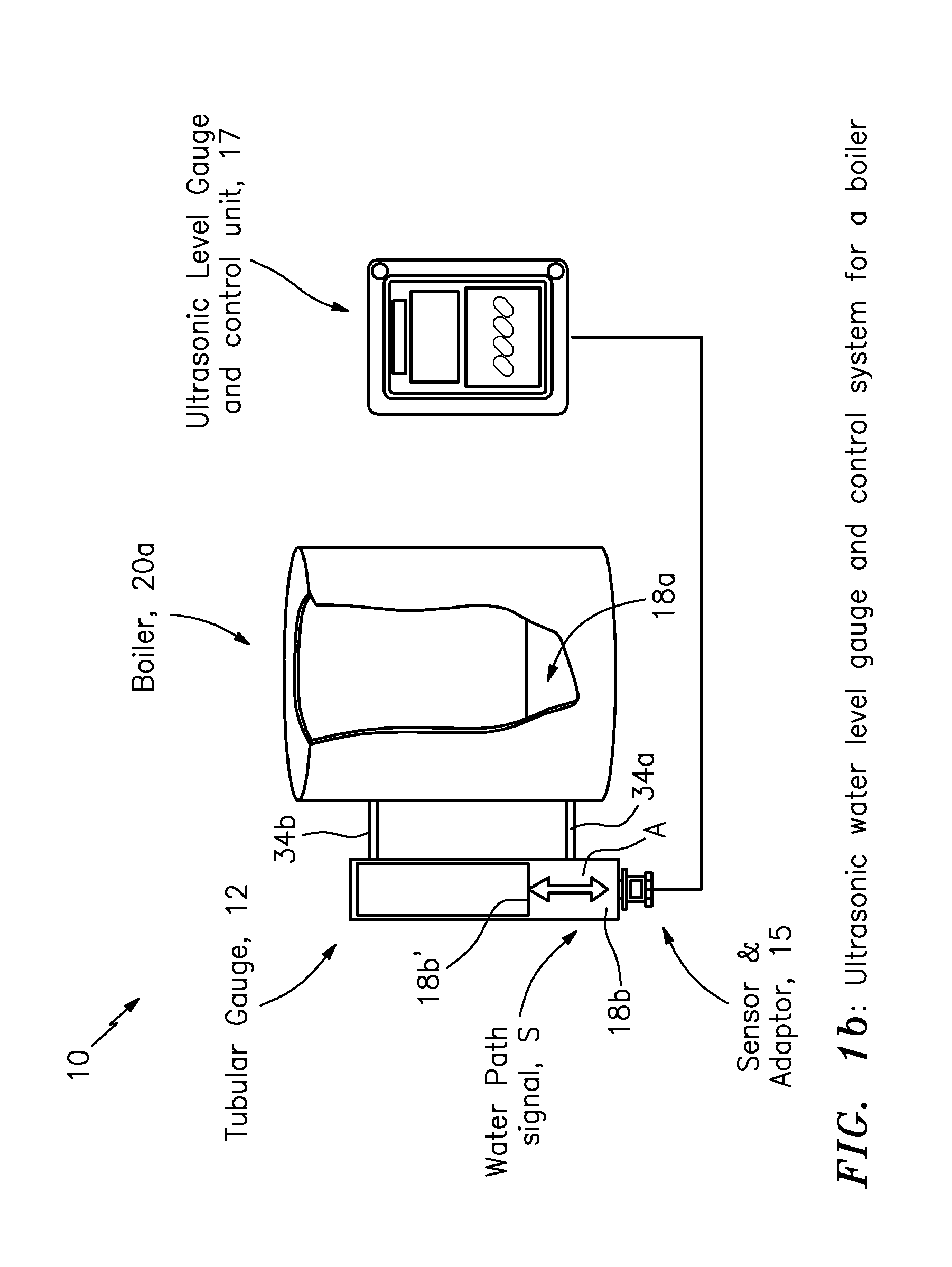
FIGS. 1a and 1b: Apparatus, e.g. an Ultrasonic Liquid Level Gauge and Control System

[0037]FIGS. 1a and 1b show, by way of example, the present invention in the form of apparatus generally indicated as 10, including an ultrasonic liquid level gauge and control system, according to some embodiments of the present invention. The apparatus 10 may comprise a gauge 12 and an ultrasonic transducing and signal processing arrangement 14. The gauge 12 may be configured to be coupled on the outside of a device 20a, 20b, such as a boiler 20a (see FIG. 1b) or a hot water tank 20b (see FIG. 6), having liquid generally indicated as 18a (e.g., water) contained therein. The gauge 12 may also configured to receive and contain a small part 18b of the liquid 18a of the device 20a, 20b. The ultrasonic transducing and signal processing arrangement 14 may be configured to reflect an ultrasonic pulse off a liquid surface 18b′ of the small part 18b of the liquid 18a of the device 20a, 20b contained in the g...


PUM


Abstract

Apparatus, including an ultrasonic liquid level gauge and control system, includes a gauge configured to be coupled on the outside of a device, having a boiler or hot water tank, having liquid contained therein. The gauge is also configured to receive and contain a small part of the liquid of the device; and an ultrasonic transducing and signal processing arrangement configured to: reflect an ultrasonic pulse off a liquid surface of the small part of the liquid of the device contained in the gauge, and determine the level of liquid in the device based at least partly on a time of flight analysis related to the ultrasonic pulse reflected off the liquid surface of the small part of the liquid of the device contained in the gauge.

Description

BACKGROUND OF THE INVENTION[0001]1. Field of the Invention[0002]The present invention relates to a method and apparatus for measuring the water level in a boiler; and more particularly, the present invention relates to a method and apparatus for measuring the water level in a boiler using an ultrasonic level gauge and control device.[0003]2. Brief Description of Related Art[0004]In current techniques for water level gauge and control for a boiler or a hot water tank, a tubular sight glass mounted on the outside of the boiler and a water level switch at each end of the boiler control water levels are the most commonly used means for most residential, commercial or industrial applications. Due to the harsh working conditions of high temperature, high pressure, high humidity and condensate, and turbulent water surface while boiling, most techniques including some ultrasonic level measurements for a liquid tank through either an air path approach or a water path approach might be unfeas...

Claims


Application Information

Patent Timeline
Patent Type & Authority Patents(United States)
IPC IPC(8): G01F23/296
CPCG01F23/02G01F23/2962
Inventor CHENG, ANDREW A.GU, JAMES J.BRANZELL, JOHN E.
Owner XYLEM IP HLDG
Why Eureka
Try Eureka