Laryngeal mask

a technology of laryngeal mask and laryngeal tube, which is applied in the direction of tracheal tubes, life-saving devices, respiratory apparatus, etc., can solve the problems of severe restriction of the size of endo-tracheal tubes or related medical devices, inability to exert the pressure necessary to maintain proper positioning, and difficult placement of masks. to achieve the effect of facilitating lung ventilation, facilitating lung ventilation, and facilitating lung ventilation

Inactive Publication Date: 2014-01-21
SALTER LABS LLC
View PDF137 Cites 7 Cited by
  • Summary
  • Abstract
  • Description
  • Claims
  • Application Information

AI Technical Summary

Problems solved by technology

Current laryngeal masks have several drawbacks in the area of placement, lung ventilation, and endotracheal intubation.
For example, during insertion and positioning, the flexible nature of the deflated ring structure and surrounding mask allows the distal end of the mask to bend back on itself, making placement difficult.
Also, once installed, the current mask designs fail to exert sufficient pressure against the larynx necessary to maintain proper positioning during intubation and ventilation.
However, these band structures severely restrict the size of the endo-tracheal tubes or related medical devices that may be passed through the flexible breathing tube.
Moreover, after insertion of an endo-tracheal tube or related medical device, it becomes difficult to remove the laryngeal mask from the patient's oropharynx without dislodging or accidentally extracting the endo-tracheal tube or medical device along with the laryngeal mask.

Method used


Image

  • Laryngeal mask
  • Laryngeal mask
  • Laryngeal mask

Examples


Embodiment Construction

[0036]The following detailed description illustrates the invention by way of example and not by way of limitation. The description will clearly enable one skilled in art to make and use the invention, describe several embodiments, adaptations, variations, alternatives, and uses of the invention including what is believed to be the best mode of carrying out the invention.

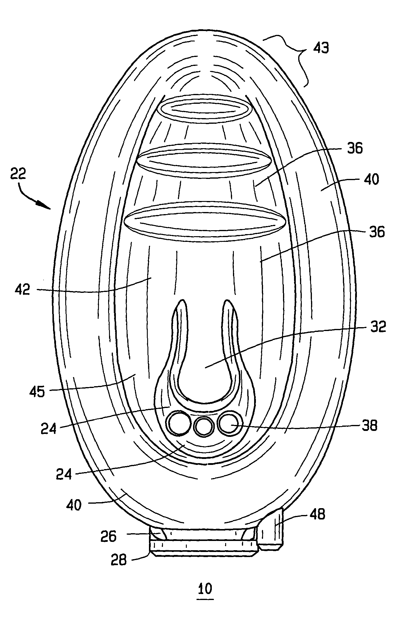
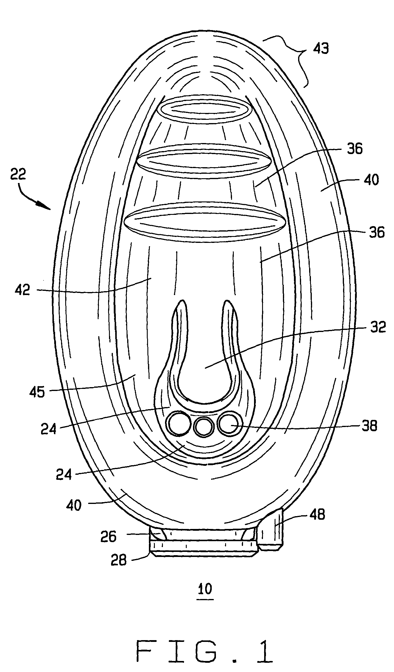
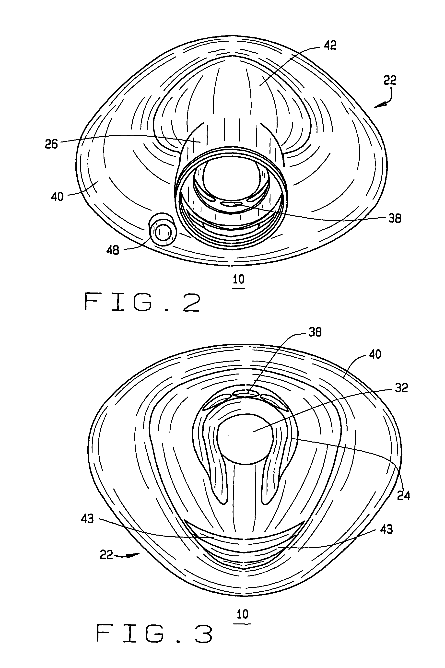
[0037]Referring to the drawings, and particularly FIGS. 1-3, a new and useful laryngeal mask 10 has been invented that provides generally the same function as current laryngeal masks, while avoiding some of the problems associated with their use. Specifically, the laryngeal masks 10 of the invention can be more securely and certainly inserted and removed, permitting the unrestricted passage of large diameter endotracheal tubes directly to the laryngeal opening, and providing alternate airways to prevent blockage of the breathing tube during patient ventilation. In accordance with the invention, a laryngeal mask 10 is...


PUM


Abstract

A laryngeal mask of the type used to facilitate lung ventilation and the insertion of endo-tracheal tubes or related medical instruments through a patient's laryngeal opening as used during general anesthesia, intensive care, or critical patient care is described that includes an inflatable positioning and a respiratory tube. The inflatable positioning shield is formed to fit within a patient's oropharynx, and has an inflatable, hollow peripheral portion, a pliable base in fluid communication with the peripheral portion, a shield recess formed after inflation of the peripheral portion, and a rear portion formed between the posterior base and the peripheral portion after inflation of the peripheral portion, wherein the posterior base has a recessed front portion. The respiratory tube has a proximal end lumen, a curved tubular body of sufficient size to permit the passage of endo-tracheal tubes or related medical instruments, and a distal end passing through and secured to the rear portion of the positioning shield. The distal end terminates at a distal lumen, which passes through and is secured to the rear portion of the positioning shield such that tubes and instruments passing through the respiratory tube will be directed into the laryngeal opening.

Description

CROSS-REFERENCE TO RELATED APPLICATIONS[0001]This is a continuation-in-part of U.S. patent application Ser. No. 09 / 829,157, filed Apr. 9, 2001, and issued as U.S. Pat. No. 6,705,321, which is a continuation-in-part of U.S. patent application Ser. No. 09 / 179,928, filed on Oct. 27, 1998, and issued as U.S. Pat. No. 6,422,239, which is a divisional of U.S. patent application Ser. No. 08 / 843,631, filed on Apr. 10, 1997, and issued as U.S. Pat. No. 5,937,860.STATEMENT REGARDING FEDERALLY SPONSORED RESEARCH OR DEVELOPMENT[0002]Not applicable.BACKGROUND OF THE INVENTION[0003]This invention relates to an artificial airway device designed to facilitate lung ventilation and the insertion of endotracheal tubes or related medical instruments into the laryngeal opening of an unconscious patient, and more specifically to a laryngeal mask designed to be placed within the oropharynx region over the laryngeal opening to conceal the circumference of the laryngeal opening against the aspiration of reg...

Claims


Application Information

Patent Timeline
Patent Type & Authority Patents(United States)
IPC IPC(8): A61M16/04A61M16/00
CPCA61M2016/0409A61M16/0463A61M2016/0431A61M2016/0445A61M16/04A61M2016/0486A61M16/0488A61M16/0445A61M16/0486A61M16/0409A61M16/0431A61M16/0484
Inventor COOK, DANIEL, J.
Owner SALTER LABS LLC
Why Eureka
Try Eureka