Fluid dispensing system with thermal control

a technology of fluid dispensing system and thermal control, which is applied in the direction of liquid handling, instruments, machines/engines, etc., can solve the problems of solution freezing at low temperatures, affecting the quality of fluid dispensing, so as to facilitate temperature control, increase and decrease the effect of volum

Inactive Publication Date: 2014-01-28
SMITH CLYDE M
View PDF14 Cites 7 Cited by
  • Summary
  • Abstract
  • Description
  • Claims
  • Application Information

AI Technical Summary

Benefits of technology

[0007]One aspect of the disclosure relates to a system for dispensing fluid. The system may include a first fluid circuit, and the first fluid circuit may include a first reservoir configured to contain a supply of a first fluid for being dispensed and a first variable volume chamber in flow communication with the first fluid circuit. The first variable volume chamber may be configured to increase and decrease in volume. The system may further include a second fluid circuit configured to provide pressure for dispensing the first fluid. The second fluid circuit may include a second reservoir configured to contain a supply of a second fluid, a pump configured to pump the second fluid within the second fluid circuit, fluid passages configured to provide fluid flow within the second fluid circuit, and a second variable volume chamber in flow communication with the second fluid circuit, the second variable volume chamber being configured to increase and decrease in volume. The second fluid circuit may be a closed-loop circuit, and the first variable volume chamber and the second variable volume chamber may be associated with one another, such that as the volume of the second variable volume chamber increases, the volume of the first variable volume chamber decreases, thereby dispensing the first fluid from the first fluid circuit. The fluid passages of the second fluid circuit may be associated with the first fluid circuit, such that flow of the second fluid in the second fluid circuit facilitates control of the temperature of the first fluid in the first fluid circuit.

Problems solved by technology

However, the use of urea-water solutions may exhibit some potential drawbacks, including, for example, the solution freezing at low temperatures and being of a corrosive nature.
In cold conditions, such thawing may take an undesirable length of time.
Flowing the second fluid may result in affecting the temperature and flow of the first fluid in the first fluid circuit.

Method used


Image

  • Fluid dispensing system with thermal control
  • Fluid dispensing system with thermal control
  • Fluid dispensing system with thermal control

Examples


Embodiment Construction

[0016]Reference will now be made in detail to exemplary embodiments. Wherever possible, the same reference numbers are used in the drawings and the description to refer to the same or like parts.

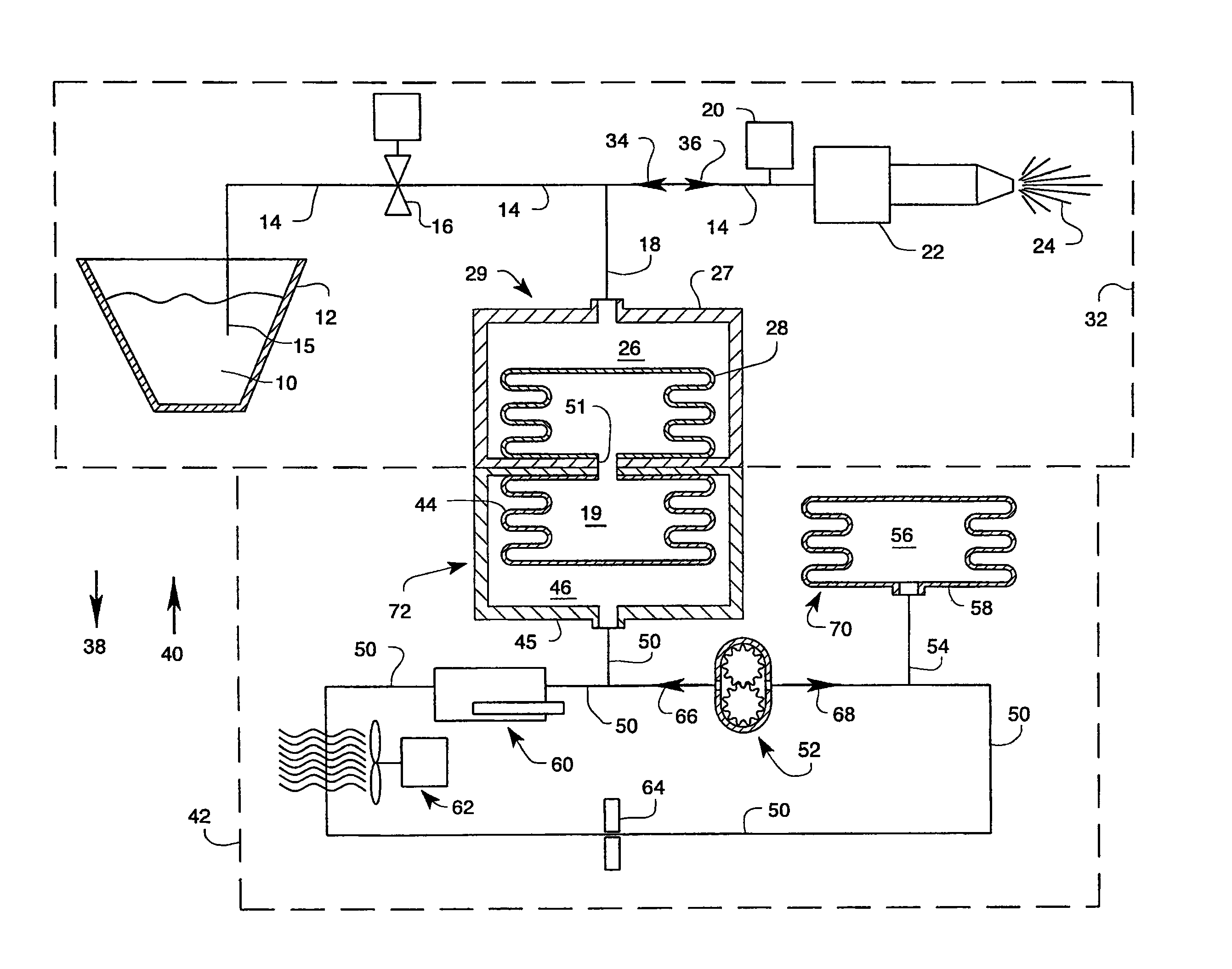
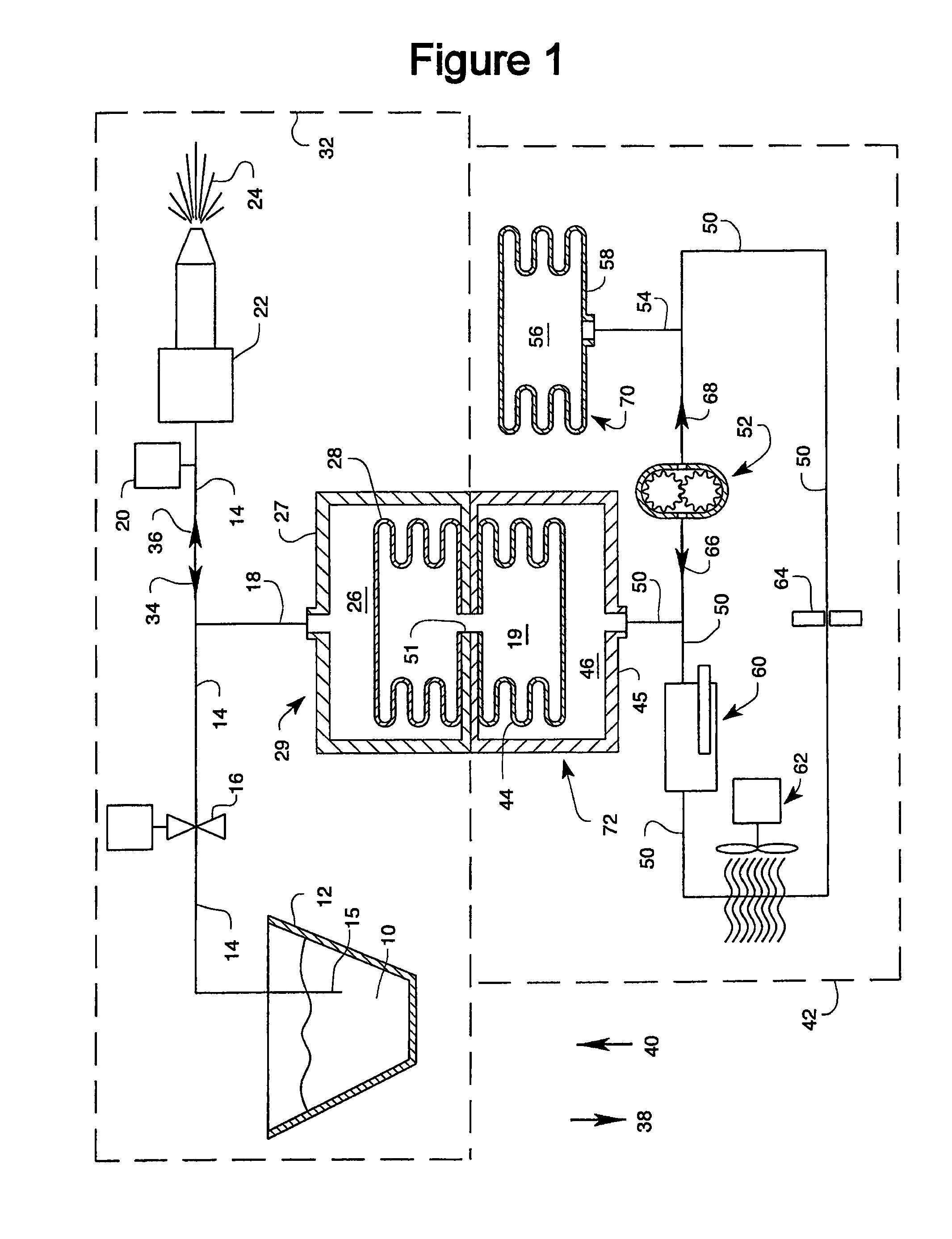
[0017]According to some embodiments of systems for dispensing fluids, the system may include first and seconds fluids, with the first fluid being dispensed and the second fluid being used to facilitate dispensing of the first fluid. According to some embodiments, the second fluid may also be used to control the temperature of the first fluid. For example, for situations in which it is desirable to dispense an intermittent spray of the first fluid, the rate of spray may be controlled by pulse-width-modulation. Examples of such situations may include, but are not limited to, beverage dispensing and operation of an SCR-emission control system on, for example, a compression ignition engine (e.g., a diesel engine), where a urea-water solution may be subject to freezing.

[0018]For example, FIG. 1 s...


PUM


Abstract

A system for dispensing fluid may include a first fluid circuit and second fluid circuit. The first fluid circuit may include a first reservoir configured to contain a supply of first fluid for being dispensed and a first variable volume chamber in flow communication with the first fluid circuit. The second fluid circuit may be configured to provide pressure for dispensing the first fluid. The second fluid circuit may include a second reservoir, a pump, fluid passages configured to provide fluid flow within the second fluid circuit, and a second variable volume chamber in flow communication with the second fluid circuit. The second fluid circuit may be a closed-loop circuit, and the first variable volume chamber and the second variable volume chamber are associated with one another, such that flow of fluid in the second circuit controls dispensing and temperature of the first fluid in the first fluid circuit.

Description

CLAIM OF PRIORITY / INCORPORATION BY REFERENCE[0001]This PCT International Application claims the right of priority to, and hereby incorporates by reference herein in its entirety, U.S. Provisional Application No. 61 / 215,581, filed May 7, 2009.FIELD OF THE DISCLOSURE[0002]The present disclosure relates to a fluid dispensing system. In particular, the present disclosure relates to a fluid dispensing system with thermal control.BACKGROUND OF THE DISCLOSURE[0003]There are a number of situations in which it may be desirable to dispense fluid in a controlled manner and such that the temperature of the dispensed fluid may be controlled, either before or during dispensing. For example, in the field of beverage dispensing, it is often desirable to be able to both dispense the beverage and control the temperature of the dispensed beverage. For example, it may be desirable to dispense beverages such as, for example, beer and soft drinks, in a cold condition, while in contrast, it may be desirab...

Claims


Application Information

Patent Timeline
Patent Type & Authority Patents(United States)
IPC IPC(8): B67D1/00
CPCF01N2610/10F01N2610/14F01N2610/1486Y02T10/24F01N3/2066F01N2610/03Y02T10/12
Inventor SMITH, CLYDE, M.
Owner SMITH CLYDE M
Why Eureka
Try Eureka