System and method of calibrating a phase-locked loop while maintaining lock

a phase-locked loop and lock technology, applied in the field of phase-locked loop calibration, can solve the problems of jitter in the output signal, affecting the performance of the pll, and being sensitive to process, voltage and temperature variations

Inactive Publication Date: 2014-01-28
QUALCOMM INC
View PDF11 Cites 1 Cited by
  • Summary
  • Abstract
  • Description
  • Claims
  • Application Information

AI Technical Summary

Benefits of technology

[0005]Systems and methods of calibrating a PLL without losing lock at the PLL are disclosed. For example, a control signal of the PLL may exceed a threshold value, indicating that the PLL has undergone a voltage or temperature fluctuation above a threshold. In response, an amount of current supplied by a calibration circuit to an oscillator of the PLL may be modified to counteract the temperature or voltage fluctuation. The amount of current may be slowly varied, thereby enabling the control signal to return below the threshold value without losing lock at the PLL. Thus, the systems and methods disclosed herein may enable the PLL to maintain lock and operate at a higher or lower voltage or temperature than during the initial power-up stage.

Problems solved by technology

However, the PLL may be sensitive to process, voltage, and temperature variations.
For example, the PLL may “lose lock” with respect to the input signal when process, temperature, or voltage variations occur within the PLL, thereby introducing jitter into the output signal.
However, during operation of the PLL, temperature or voltage changes may occur that shift the PLL outside the operating range, resulting in performance degradation at the PLL.
The rise in temperature may result in the PLL losing lock with an input signal and introducing jitter into an output signal of the PLL.
Moreover, recalibrating the PLL using initial calibration methods may cause the PLL to lose lock with the input signal, resulting in a waiting period while the recalibrated PLL attempts to reacquire lock to the input signal.

Method used


Image

  • System and method of calibrating a phase-locked loop while maintaining lock
  • System and method of calibrating a phase-locked loop while maintaining lock
  • System and method of calibrating a phase-locked loop while maintaining lock

Examples


Embodiment Construction

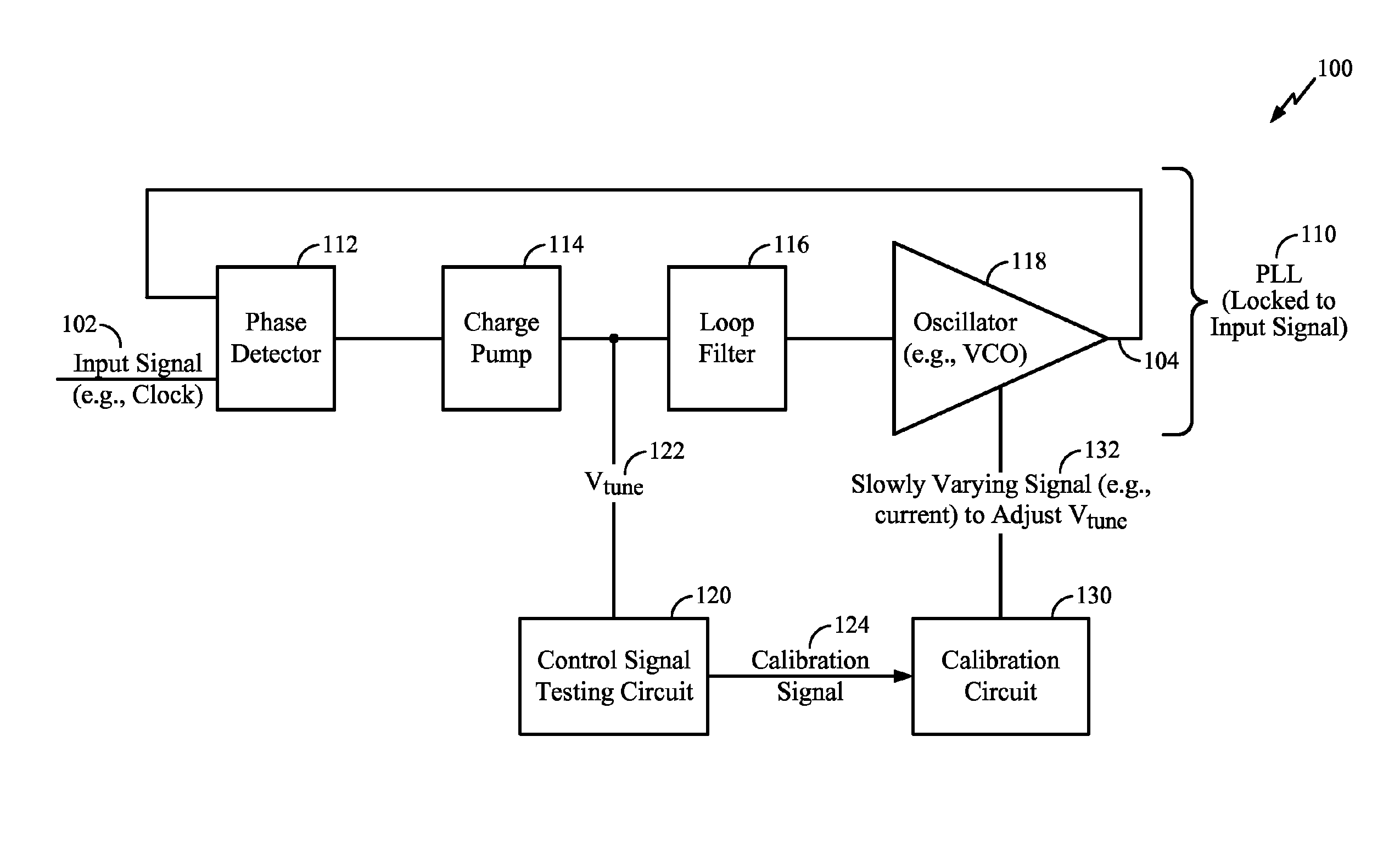
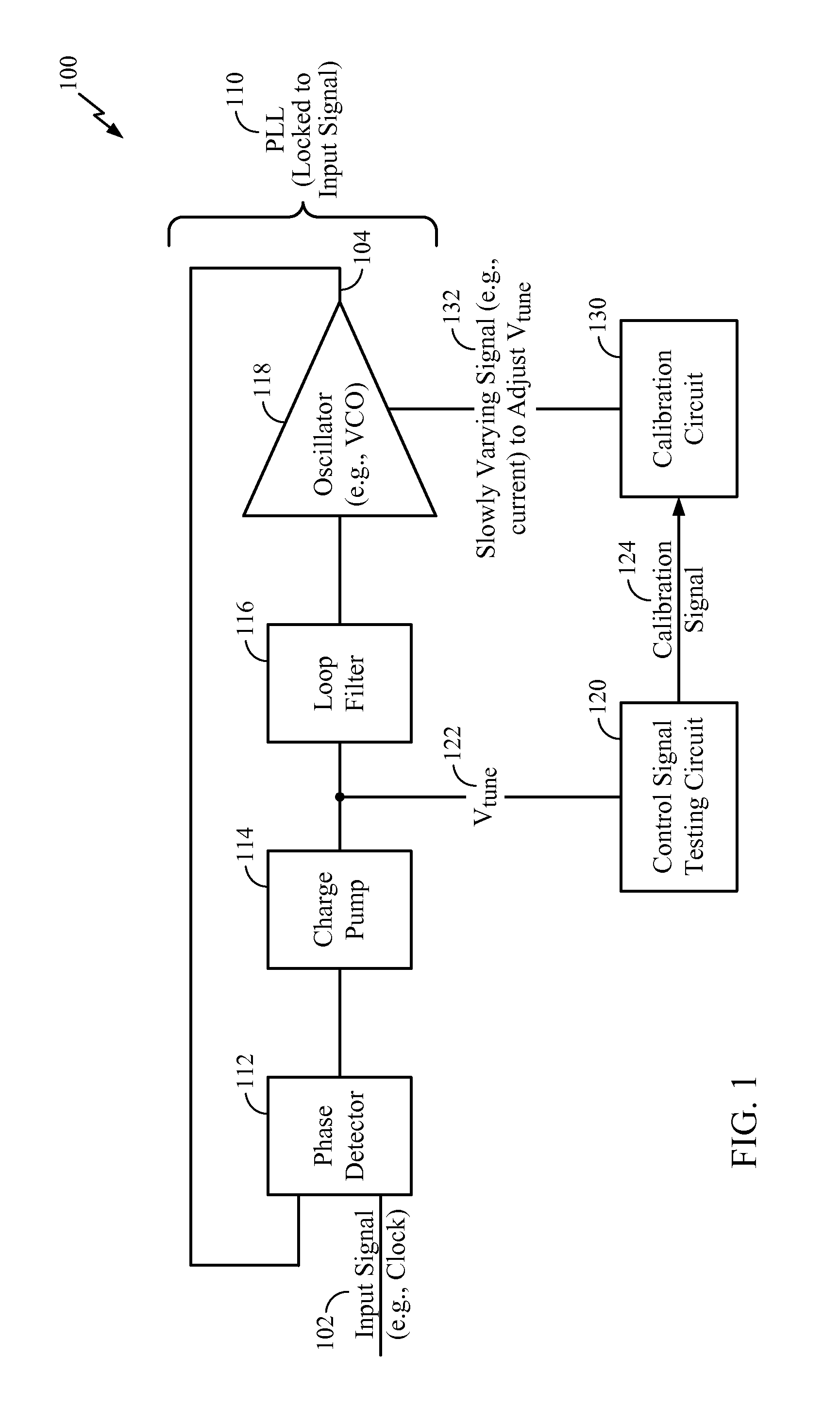
[0019]Referring to FIG. 1, a particular illustrative embodiment of a system of calibrating a phase-locked loop (PLL) while maintaining lock is disclosed and generally designated 100. The system 100 includes a PLL 110 coupled to a control signal testing circuit 120 and to a calibration circuit 130.

[0020]The PLL 110 may receive an input signal 102 and may produce an output signal 104. For example, the input signal 102 may be a clock signal (e.g., having a frequency of 100 Hz). When locked to the input signal 102, the output signal 104 produced by the PLL 110 may have the same frequency as the input signal 102 (e.g., 100 Hz) or may have a multiple of the frequency of the input signal 102 (e.g., 200 Hz, 500 Hz, 10 MHz, 1 GHz, etc.).

[0021]The PLL 110 may include a phase detector 112, a charge pump 114, a loop filter 116 (e.g., a low-pass filter), and an oscillator 118 (e.g., a voltage-controlled oscillator (VCO)). When the frequency of the output signal 104 is a multiple of the frequency...


PUM


Abstract

A method of calibrating a phase-locked loop (PLL) while maintaining lock includes detecting that a control signal to an oscillator in a PLL has exceeded a threshold value while the PLL is locked to an input signal. In response, an operating current of the oscillator is adjusted to return the control signal below the threshold value while maintaining lock of the PLL to the input signal. Adjusting the operating current includes slowly varying an output current of a calibration circuit coupled to the PLL, enabling the PLL to maintain lock to the input signal during adjustment of the operating current.

Description

I. FIELD[0001]The present disclosure is generally related to calibration of phase-locked loops.II. DESCRIPTION OF RELATED ART[0002]Advances in technology have resulted in smaller and more powerful computing devices. For example, there currently exist a variety of portable personal computing devices, including wireless computing devices, such as portable wireless telephones, personal digital assistants (PDAs), and paging devices that are small, lightweight, and easily carried by users. More specifically, portable wireless telephones, such as cellular telephones and Internet protocol (IP) telephones, can communicate voice and data packets over wireless networks. Further, many such wireless telephones include other types of devices that are incorporated therein. For example, a wireless telephone can also include a digital still camera, a digital video camera, a digital recorder, and an audio file player. Also, such wireless telephones can process executable instructions, including soft...

Claims


Application Information

Patent Timeline
Patent Type & Authority Patents(United States)
IPC IPC(8): H03L7/00
CPCH03L7/0891
Inventor MURPHY, GLENN A.KONG, XIAOHUADANG, NAM V.
Owner QUALCOMM INC
Why Eureka
Try Eureka