Oscillator applied to a control circuit of a power converter and control method thereof

a control circuit and oscillator technology, applied in the direction of electric variable regulation, process and machine control, instruments, etc., can solve the problems of inability to increase the conversion efficiency of the power converter, the output voltage of the secondary side of the power converter corresponding to the load is poor, and the ripple of the output voltage cannot be suppressed, so as to achieve slow variation and slow variation. , the effect of slow variation

Active Publication Date: 2017-05-02
LEADTREND TECH
View PDF1 Cites 0 Cited by
  • Summary
  • Abstract
  • Description
  • Claims
  • Application Information

AI Technical Summary

Benefits of technology

[0009]The present invention provides an oscillator applied to a control circuit of a power converter and a control method thereof. The oscillator and the control method can utilize a compensation module to output or sink an adjustment current according to a compensation voltage corresponding to a load of a secondary side of the power converter, a DC voltage of a primary side of the power converter, and a reference voltage, and utilize an oscillation module to output a clock signal according to the compensation voltage, a control voltage, and the adjustment current, wherein the clock signal can be slowly varied with the compensation voltage when the load is middle or heavy. Because the clock signal can be slowly varied with the compensation voltage when the load is middle or heavy, a frequency of a gate control signal generated by a gate control signal generation unit within the control circuit to a power switch of the primary side of the power converter can be also slowly varied with the compensation voltage when the load is middle or heavy. Because the frequency of the gate control signal can be also slowly varied with the compensation voltage when the load is middle or heavy, compared to the prior art, the present invention has advantages as follows: first, a response of an output voltage of the secondary side of the power converter corresponding to the load is better; second, ripples of the output voltage can be suppressed; third, conversion efficiency of the power converter can be increased.

Problems solved by technology

When the compensation voltage is greater than the second predetermined voltage, the load is middle or heavy, but the frequency of the pulse width modulation signal is the second fixed value, the prior art has disadvantages as follows when the compensation voltage is greater than the second predetermined voltage: first, a response of an output voltage of the secondary side of the power converter corresponding to the load is poorer; second, ripples of the output voltage cannot be suppressed; third, conversion efficiency of the power converter cannot be increased.

Method used


Image

  • Oscillator applied to a control circuit of a power converter and control method thereof
  • Oscillator applied to a control circuit of a power converter and control method thereof
  • Oscillator applied to a control circuit of a power converter and control method thereof

Examples


first embodiment

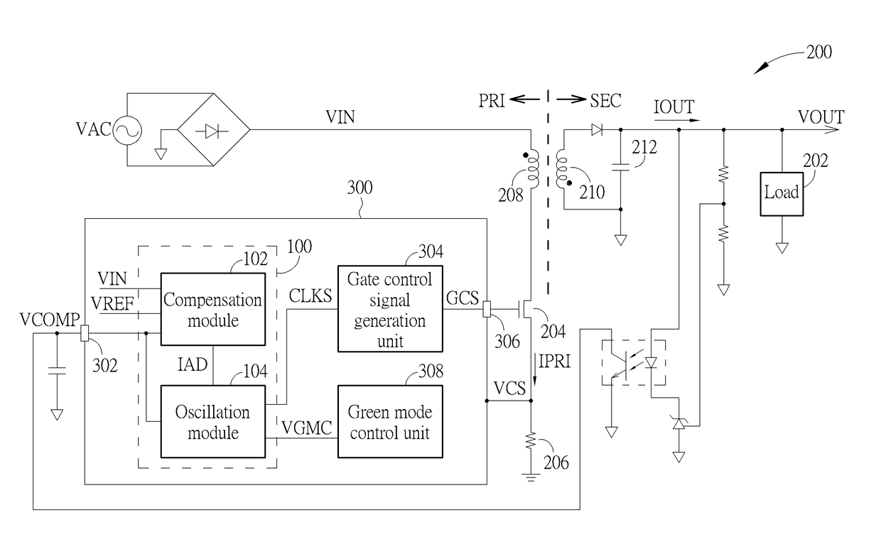
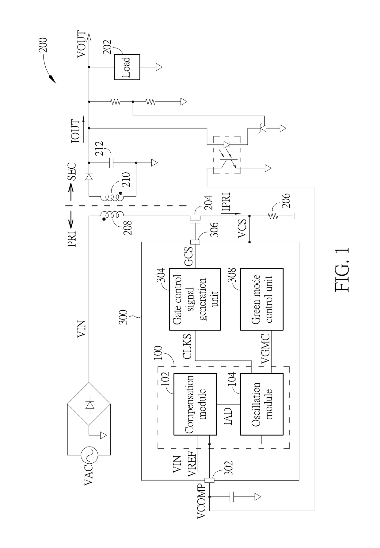
[0022]Please refer to FIG. 1. FIG. 1 is a diagram illustrating an oscillator 100 applied to a control circuit 300 of a power converter 200 according to the present invention. As shown in FIG. 1, the oscillator 100 includes a compensation module 102 and an oscillation module 104. The compensation module 102 is used for outputting or sinking an adjustment current IAD according to a compensation voltage VCOMP corresponding to a load 202 of a secondary side SEC of the power converter 200, a direct current (DC) voltage VIN of a primary side PRI of the power converter 200, and a reference voltage VREF, wherein the DC voltage VIN corresponds to an alternating current voltage VAC, the compensation module 102 receives the compensation voltage VCOMP through a compensation pin 302, and in one embodiment of the present invention, the reference voltage VREF can be equal to 100V. But, the present invention is not limited to the reference voltage VREF being 100V. The oscillation module 104 is used...

second embodiment

[0042]Please refer to FIG. 9. FIG. 9 is a diagram illustrating a relationship between the compensation voltage VCOMP and the frequency FR of the gate control signal GCS according to the present invention. As shown in FIG. 9, the oscillator 100 can be appropriately modified according to the above mentioned description corresponding to FIGS. 3-5 to make the frequency FR of the gate control signal GCS be varied with the compensation voltage VCOMP when the compensation voltage VCOMP is between the first predetermined voltage FPV and the second predetermined voltage SPV (the voltage range VS2), between the second predetermined voltage SPV and a third predetermined voltage TPV (the voltage range VS3), and between the third predetermined voltage TPV and a fourth predetermined voltage FOPV (a voltage range VS4), the frequency FR of the gate control signal GCS is the first fixed value FV when the compensation voltage VCOMP is less than the first predetermined voltage FPV, and the frequency F...

third embodiment

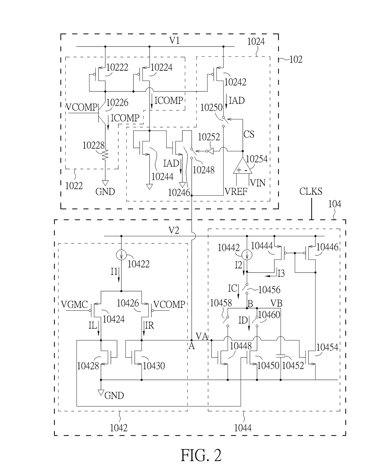
[0043]Please refer to FIGS. 1-8 and FIG. 11. FIG. 11 is a flowchart illustrating a control method of an oscillator according to a The control method in FIG. 11 is illustrated using the oscillator 100, the power converter 200, and the control circuit 300 in FIG. 1, and the compensation module 102, the voltage-to-current converting unit 1022, the adjustment current generation unit 1024, the oscillation module 104, the differential unit 1042, and the clock signal generation unit 1044 in FIG. 2. Detailed steps are as follows:

[0044]Step 1100: Start.

[0045]Step 1102: The voltage-to-current converting unit 1022 generates the compensation current ICOMP according to the compensation voltage VCOMP.

[0046]Step 1104: The differential unit 1042 generates the control current according to the compensation voltage VCOMP and the control voltage VGMC, go to Step 1110 or Step 1114.

[0047]Step 1106: If the DC voltage VIN is less than the reference voltage VREF; if yes, go to Step 1108; if no, go to Step ...


PUM


Abstract

An oscillator applied to a control circuit of a power converter includes a compensation module and an oscillation module. The compensation module outputs or sinks an adjustment current according to a compensation voltage corresponding to a load, a direct current voltage of a primary side of the power converter, and a reference voltage. The oscillation module outputs a clock signal according to the compensation voltage, a control voltage, and the adjustment current. The control circuit generates a gate control signal to a power switch of the primary side according to the clock signal. When the compensation voltage is less than a first predetermined voltage, a frequency of the gate control signal is a first fixed value, and when the compensation voltage is between the first predetermined voltage and a second predetermined voltage and greater than the second predetermined voltage, the frequency is varied with the compensation voltage.

Description

CROSS REFERENCE TO RELATED APPLICATIONS[0001]This application claims the benefit of U.S. Provisional Application No. 62 / 036,632, filed on Aug. 13, 2014 and entitled “Dynamic PWM operation to improved efficiency, dynamic load and output ripple,” the contents of which are incorporated herein by reference.BACKGROUND OF THE INVENTION[0002]1. Field of the Invention[0003]The present invention relates to an oscillator applied to a control circuit of a power converter and a control method thereof, and particularly to an oscillator and a control method thereof that can control a frequency of a gate control signal to be varied with a compensation voltage when a load is middle or heavy.[0004]2. Description of the Prior Art[0005]A control circuit applied to a power converter provided by the prior art can output a pulse width modulation signal to a power switch of a primary side of the power converter in pulse width modulation mode, wherein a frequency of the pulse width modulation signal is a f...

Claims


Application Information

Patent Timeline
Patent Type & Authority Patents(United States)
IPC IPC(8): H02M3/33H02M3/335H02M1/00
CPCH02M3/33507H02M2001/0025H02M2001/0048Y02B70/1491H02M1/0025H02M1/0048Y02B70/10
Inventor TSOU, MING-CHANGTSAI, MENG-JENCHANG, CHIH-CHI
Owner LEADTREND TECH
Why Eureka
Try Eureka