Oscillator applied to a control circuit of a power converter and control method thereof
a control circuit and oscillator technology, applied in the direction of pulse generators, pulse techniques, instruments, etc., can solve the problems of inability to increase the conversion efficiency of the power converter, the output voltage response of the secondary side of the power converter corresponding to the load is poor, and the ripple of the output voltage cannot be suppressed, so as to achieve slow variation and slow variation, the effect of suppressing the ripple of the output voltag
- Summary
- Abstract
- Description
- Claims
- Application Information
AI Technical Summary
Benefits of technology
Problems solved by technology
Method used
Image
Examples
first embodiment
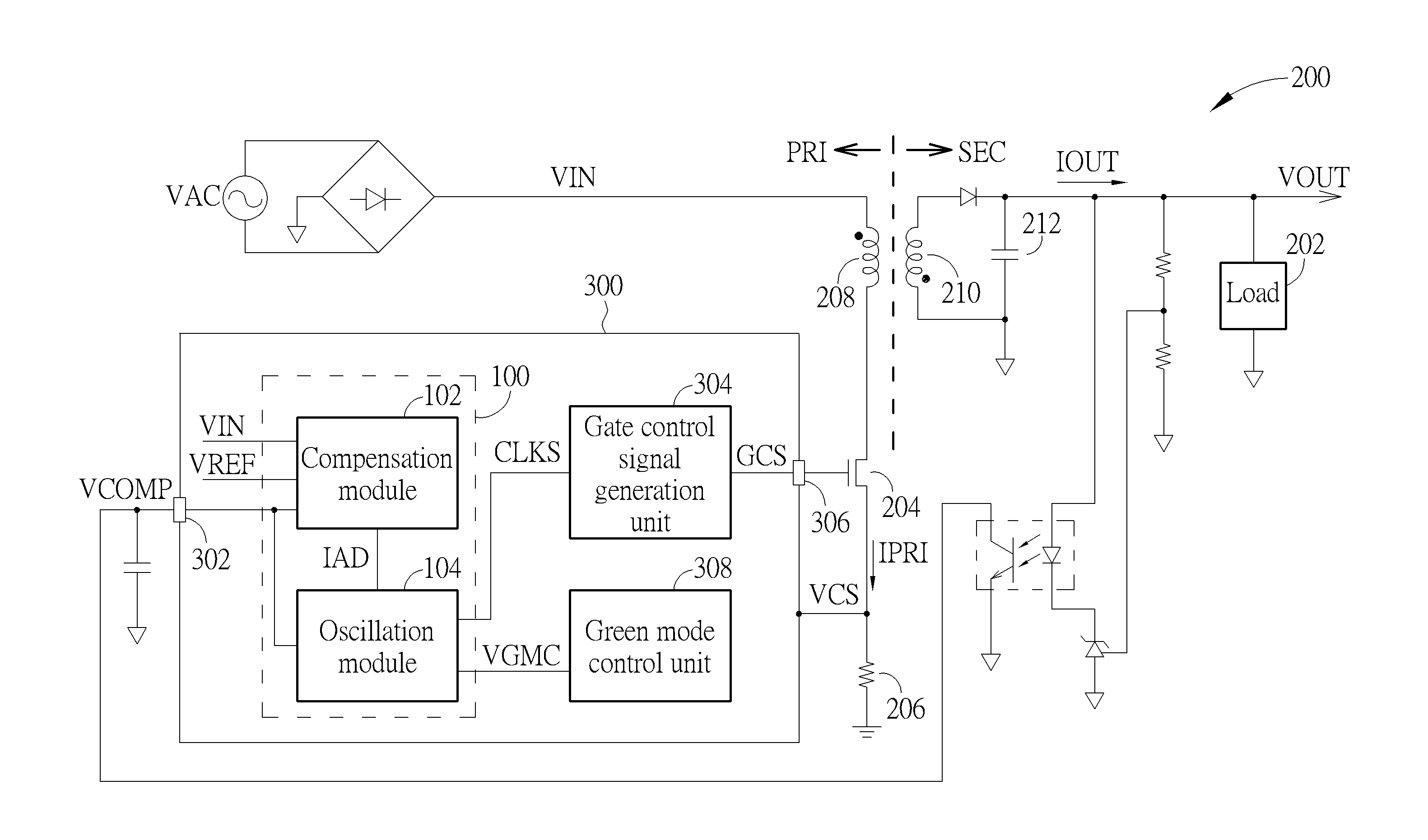
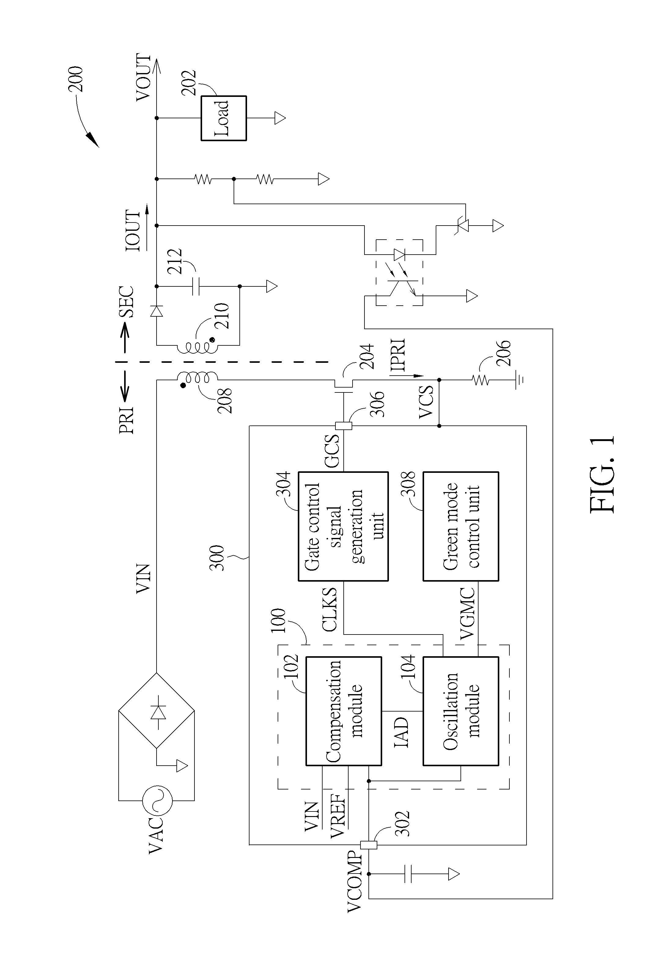
[0022]Please refer to FIG. 1. FIG. 1 is a diagram illustrating an oscillator 100 applied to a control circuit 300 of a power converter 200 according to the present invention. As shown in FIG. 1, the oscillator 100 includes a compensation module 102 and an oscillation module 104. The compensation module 102 is used for outputting or sinking an adjustment current IAD according to a compensation voltage VCOMP corresponding to a load 202 of a secondary side SEC of the power converter 200, a direct current (DC) voltage VIN of a primary side PRI of the power converter 200, and a reference voltage VREF, wherein the DC voltage VIN corresponds to an alternating current voltage VAC, the compensation module 102 receives the compensation voltage VCOMP through a compensation pin 302, and in one embodiment of the present invention, the reference voltage VREF can be equal to 100V. But, the present invention is not limited to the reference voltage VREF being 100V. The oscillation module 104 is used...
second embodiment
[0039]Please refer to FIG. 9. FIG. 9 is a diagram illustrating a relationship between the compensation voltage VCOMP and the frequency FR of the gate control signal GCS according to the present invention. As shown in FIG. 9, the oscillator 100 can be appropriately modified according to the above mentioned description corresponding toFIGS. 3-5 to make the frequency FR of the gate control signal GCS be varied with the compensation voltage VCOMP when the compensation voltage VCOMP is between the first predetermined voltage FPV and the second predetermined voltage SPV (the voltage range VS2), between the second predetermined voltage SPV and a third predetermined voltage TPV (the voltage range VS3), and between the third predetermined voltage TPV and a fourth predetermined voltage FOPV (a voltage range VS4), the frequency FR of the gate control signal GCS is the first fixed value FV when the compensation voltage VCOMP is less than the first predetermined voltage FPV, and the frequency FR...
third embodiment
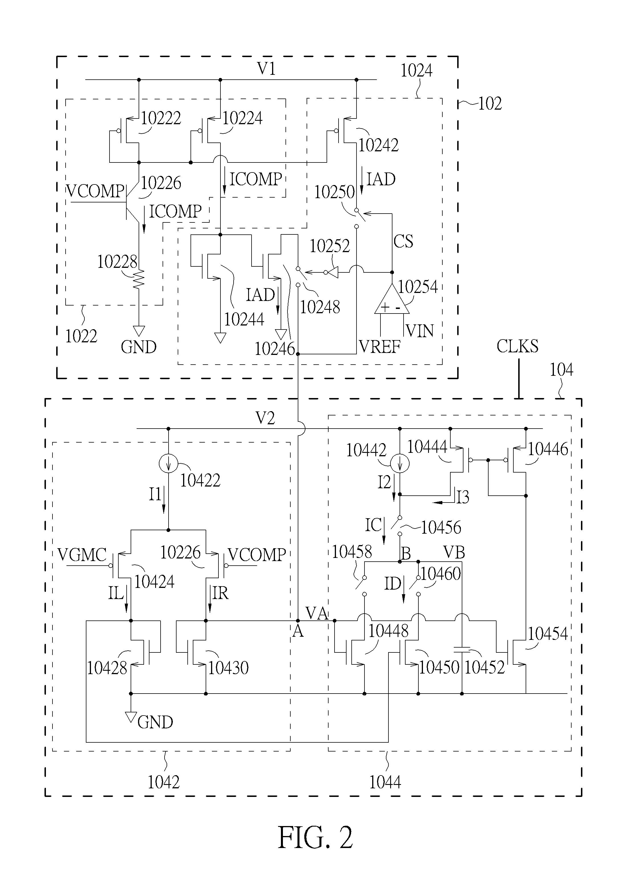
[0040]Please refer to FIGS. 1-8 and FIG. 11. FIG. 11 is a flowchart illustrating a control method of an oscillator according to a The control method in FIG. 11 is illustrated using the oscillator 100, the power converter 200, and the control circuit 300 in FIG. 1, and the compensation module 102, the voltage-to-current converting unit 1022, the adjustment current generation unit 1024, the oscillation module 104, the differential unit 1042, and the clock signal generation unit 1044 in FIG. 2. Detailed steps are as follows:
[0041]Step 1100: Start.
[0042]Step 1102: The voltage-to-current converting unit 1022 generates the compensation current ICOMP according to the compensation voltage VCOMP.
[0043]Step 1104: The differential unit 1042 generates the control current according to the compensation voltage VCOMP and the control voltage VGMC, go to Step 1110 or Step 1114.
[0044]Step 1106: If the DC voltage VIN is less than the reference voltage VREF; if yes, go to Step 1108; if no, go to Step ...
PUM
 Abstract
Description
Claims
Application Information
 - R&D
- Intellectual Property
- Life Sciences
- Materials
- Tech Scout
- Unparalleled Data Quality
- Higher Quality Content
- 60% Fewer Hallucinations
Browse by: Latest US Patents, China's latest patents, Technical Efficacy Thesaurus, Application Domain, Technology Topic, Popular Technical Reports.
© 2025 PatSnap. All rights reserved.Legal|Privacy policy|Modern Slavery Act Transparency Statement|Sitemap|About US| Contact US: help@patsnap.com


