Labeling apparatus having a pivotable base plate with feed wheel

a technology of pivoting base plate and labeling apparatus, which is applied in the direction of identification means, instruments, seals, etc., can solve the problems of preventing the possibility of adjustment or correction of the dispensing position, affecting the appearance of the label, and affecting the print imag

Inactive Publication Date: 2010-07-29
CHECKPOINT SYST INC
View PDF5 Cites 1 Cited by
  • Summary
  • Abstract
  • Description
  • Claims
  • Application Information

AI Technical Summary

Benefits of technology

[0038]In a further aspect of the present invention the guide roller includes two integrally formed axle stubs snap-fitted into associated bores in sidewalls of the base plate so that the guide roller can be mounted and demounted just as easily as the feed wheel.
[0039]In one aspect of the label web according to the present invention the pitch of the longitudinal edges of the carrier web equals the label length so that the outer contour of the labels can be varied as desired with particular ease.

Problems solved by technology

In the long run, a feed mechanism using a feed wheel basically operates more reliably than a feed mechanism using a transport slide since the latter' s function may be impaired by paper shreds.
On the other hand, the slits required for engagement of the sprockets of the feed wheel may impair the appearance of the label.
A particular problem is the fixed length of feed in both known types of labeling apparatus, which is the reason why only labels of a specified length can be processed.
In addition, this also prevents the possibility for the dispensing position to be adjusted or corrected, for example in order for the print mechanism to effect printing precisely in a preprinted zone of the label.
Moreover, the feed mechanism with slide is only suitable for use with one particular type of label in which the label pitch is in a defined phase relationship to the pitch of the outer contour of the longitudinal edges of the carrier web.
If the slits were prefabricated anywhere within the label area, they would adversely affect the print image.
Furthermore, interposition of the swivel lever allows neither adjustment nor correction of the dispensing position.

Method used


Image

  • Labeling apparatus having a pivotable base plate with feed wheel
  • Labeling apparatus having a pivotable base plate with feed wheel
  • Labeling apparatus having a pivotable base plate with feed wheel

Examples


Embodiment Construction

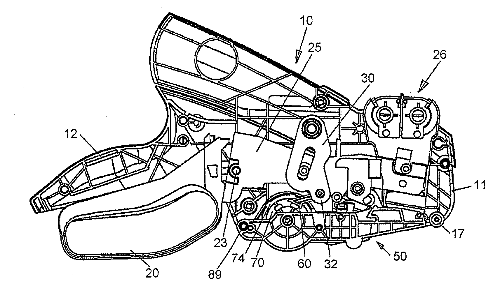
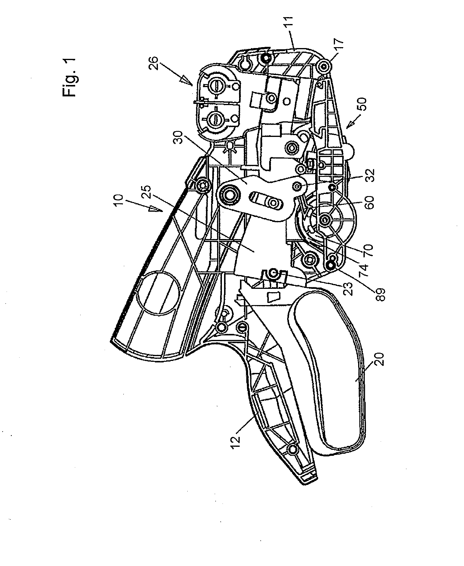
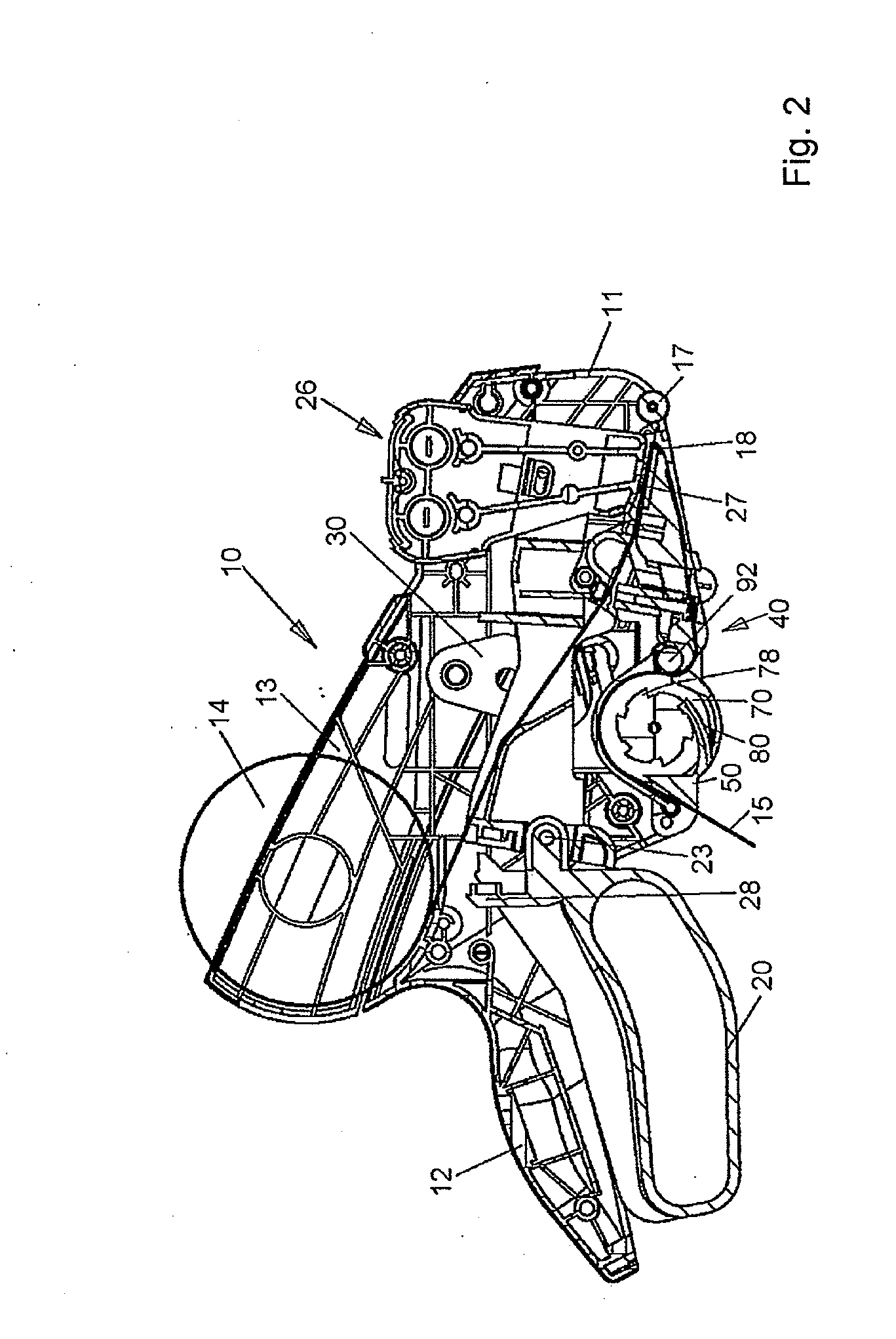
[0056]The labeling apparatus according to the present invention illustrated in FIGS. 1-3 and generally designated as 10 is similar in construction to a labeling apparatus according to the document DE 103 58 318 A1 initially cited, except for the construction of a base plate 50 carrying a feed mechanism, generally designated as 40, for a carrier web 15, and except for a feed pawl 60 which is pivotable through intermediate members by an operating lever 20 of the labeling apparatus 10. Therefore, with the exception of the base plate 50 with its feed mechanism 40, the labeling apparatus 10 will be described with reference to FIGS. 1-4 only to the extent necessary for an understanding of the present invention. The remaining figures will be described subsequently, illustrating the base plate 50 with the feed mechanism 40 arranged on it and a label web in detail.

[0057]The labeling apparatus 10 illustrated in FIGS. 1-3 includes a casing 11 formed of two plastic shells fitted together and ha...


PUM

PropertyMeasurementUnit
phase relationshipaaaaaaaaaa
flexibleaaaaaaaaaa
areaaaaaaaaaaa

Abstract

The present invention is directed to a labeling apparatus designed to dispense and apply self-adhesive labels arranged on a carrier web, a base plate suitable therefor and a label web. A feed wheel for the carrier web is rotatably mounted on the base plate and has at both its end faces a ring of axial pins engageable by an operating lever pivotally mounted on a casing of the labeling apparatus in order to drive the feed wheel in increments. The feed wheel has a generating surface with two rings of radial projections in the form of knobs adapted to make positive engagement with recesses or cutouts of the carrier web. Instead of using knobs as projections, it is also possible to provide sprockets on the feed wheel which are adapted to make positive engagement with slits in the carrier web. The base plate is configured as an interchangeable base plate which is selectable in dependence upon the phase relationship of the rings of projections to the rings of axial pins of the feed wheel.

Description

CROSS-REFERENCE TO RELATED APPLICATIONS[0001]This utility application claims the benefit under 35 U.S.C. §119(e) of Provisional Application Ser. No. 61 / 147,652 filed on Jan. 27, 2009 entitled LABELING APPARATUS HAVING A PIVOTABLE BASE PLATE WITH FEED WHEEL and whose entire disclosure is incorporated by reference herein.BACKGROUND OF THE INVENTION[0002]1. Field of Invention[0003]This invention relates to a labeling apparatus designed to dispense and apply self-adhesive labels arranged on a carrier web in which a feed wheel for the carrier web is rotatably mounted on a base plate and drivable in increments by an operating lever pivotally mounted on a casing of the labeling apparatus, in which the feed wheel has a generating surface with at least one ring of radial projections for positive engagement with the carrier web and has at both its end faces a ring of axial pins engageable by a feed pawl pivotal by the operating lever, and in which the base plate is configured to be swung away...

Claims


Application Information

Patent Timeline
Patent Type & Authority Applications(United States)
IPC IPC(8): B65C9/18B32B7/12
CPCB65C11/0247B65C2210/0067G09F3/10Y10T428/1495Y10T156/1707
Inventor BAUMBUSCH, MICHAEL
Owner CHECKPOINT SYST INC
Why Eureka
Try Eureka