Method for operating a cooling system of a motor vehicle with cooling capacity control

Pending Publication Date: 2022-11-17
DR ING H C F PORSCHE AG
View PDF4 Cites 0 Cited by
  • Summary
  • Abstract
  • Description
  • Claims
  • Application Information

AI Technical Summary

Benefits of technology

The method described in this patent proposes to regulate the cooling power of a refrigerant circuit based on the temperature of the coolant and the temperature of the components being cooled. This approach ensures a slow and gradual adjustment of the cooling power, as compared to the rapid changes in temperature that can occur when components are suddenly cooled. This damping effect helps protect the components from sudden changes in temperature and prevents cooling system failures. The regulation of the cooling power is done by defining multiple temperature windows and associating a cooling power with each window. The method also takes into account the feed temperature of the coolant and the temporal development of the feed temperature. Overall, this approach provides improved protection against damage from sudden temperature changes and results in more efficient and robust power regulation.

Problems solved by technology

A problem is however that the temperatures of the components to be cooled can vary in a highly dynamic manner, in particular if they are components of an electric drive system of a partially electrically or electrically operated vehicle.
In particular the power electronics are here often subjected to highly dynamic changes in temperature, that is to say changes in temperature over short time scales.
In the case of changes in temperature over short time scales of the components to be cooled, regulation of the cooling power of the refrigerant circuit in a manner dependent on the temperature of the component to be cooled is disadvantageous since this leads to a variation in cooling power which is likewise highly dynamic, this in turn leading to an increased energy requirement and moreover to greater loading of the components of the cooling system, in particular of the refrigerant circuit.

Method used


Image

  • Method for operating a cooling system of a motor vehicle with cooling capacity control
  • Method for operating a cooling system of a motor vehicle with cooling capacity control

Examples


Embodiment Construction

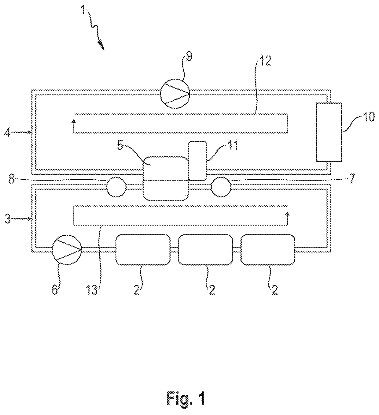
[0029]FIG. 1 shows a cooling system 1 according to aspects of the invention, wherein said cooling system 1 has a coolant circuit 3 and a refrigerant circuit 4, wherein the coolant circuit 3 serves for cooling the three components 2. In the present case, the components 2 are electrified components, for example are power electronics or components of power electronics or are a high-voltage battery. The refrigerant circuit 4 and the coolant circuit 3 are coupled thermally to one another via a heat exchanger 5. The refrigerant circuit 4 has a compressor 9, a condenser 10 and an expansion valve 11. The refrigerant of the refrigerant circuit 3 circulates clockwise in the refrigerant circuit 4, as is indicated by the arrow 12. The coolant circuit 3 has a conveying device 6 for conveying a coolant in the coolant circuit 3, wherein the coolant circulates counterclockwise in the coolant circuit 3, as is indicated by the arrow 13. The cooling system 1 has a temperature sensor 7 for measuring a ...


PUM


Abstract

A method for operating a cooling system of a motor vehicle for cooling at least one component, a cooling system of a motor vehicle for cooling at least one component, and a motor vehicle having such a cooling system. The cooling system has a coolant circuit and a refrigerant circuit. The coolant circuit serves for cooling the at least one component and the refrigerant circuit and the coolant circuit are coupled thermally to one another via a heat exchanger. The coolant circuit has a conveying device for conveying a coolant in the coolant circuit. A cooling power of the refrigerant circuit can be regulated. The regulation of the cooling power of the refrigerant circuit is realized in a manner dependent on a return temperature of the coolant and / or on a temporal development of the return temperature of the coolant.

Description

CROSS-REFERENCE TO RELATED APPLICATION[0001]This application claims priority to German Patent Application No. 10 2021 112 472.7, filed May 12, 2021, the content of such application being incorporated by reference herein in its entirety.FIELD OF THE INVENTION[0002]The present invention relates to a method for operating a cooling system of a motor vehicle for cooling at least one component. The cooling system is in particular a cooling system of an electrically operated or partially electrically operated motor vehicle. The invention furthermore relates to a cooling system of a motor vehicle for cooling at least one component, and to a motor vehicle having such a cooling system.BACKGROUND OF THE INVENTION[0003]Cooling systems for motor vehicles are known in various embodiments from the prior art. Cooling systems of said type are used in particular in electrically or partially electrically operated vehicles, and thus in hybrid or electric vehicles. In said vehicles, cooling systems of s...

Claims


Application Information

Patent Timeline
IPC IPC(8): B60H1/32B60H1/00
CPCB60H1/3205B60H1/00385B60H1/3227B60H2001/3255F25B41/40F25B49/02H01M10/613H01M10/625H01M10/635H01M10/6556B60H2001/00307B60H1/00278B60H1/32281B60H2001/3272B60K2001/005
Inventor RAPP, TOBIASSIEGEL, SAMUELADAM, ANDREASDANNOWSKI, MARCELBROZICEK, CHRISTIAN
Owner DR ING H C F PORSCHE AG
Why Eureka
Try Eureka