Hand-operated cutting apparatus

a cutting apparatus and hand-operated technology, applied in the direction of mechanical control devices, instruments, process and machine control, etc., can solve the problems of time-consuming and labor-intensive cutting operation, uniform shapes and sizes of objects, and labor-intensive operation of such apparatuses, so as to achieve labor-saving and convenient operation of the apparatus

Active Publication Date: 2014-02-04
COSSO INT
View PDF17 Cites 3 Cited by
  • Summary
  • Abstract
  • Description
  • Claims
  • Application Information

AI Technical Summary

Benefits of technology

[0017]With the hand-operated cutting apparatus of the present invention, users may cut the objects step by step, therefore, the resultant size of the objects could be controlled perfectly, and the operation of the apparatus is convenient and labor saving.

Problems solved by technology

However, such kind of cutting operation is time-consuming and laborious, and the resultant shapes and sizes of the objects are not uniform.
Such kind of special cutting apparatuses may control the resultant shape of the objects, however, the operation of such apparatuses is still laborious.

Method used


Image

  • Hand-operated cutting apparatus
  • Hand-operated cutting apparatus
  • Hand-operated cutting apparatus

Examples


Embodiment Construction

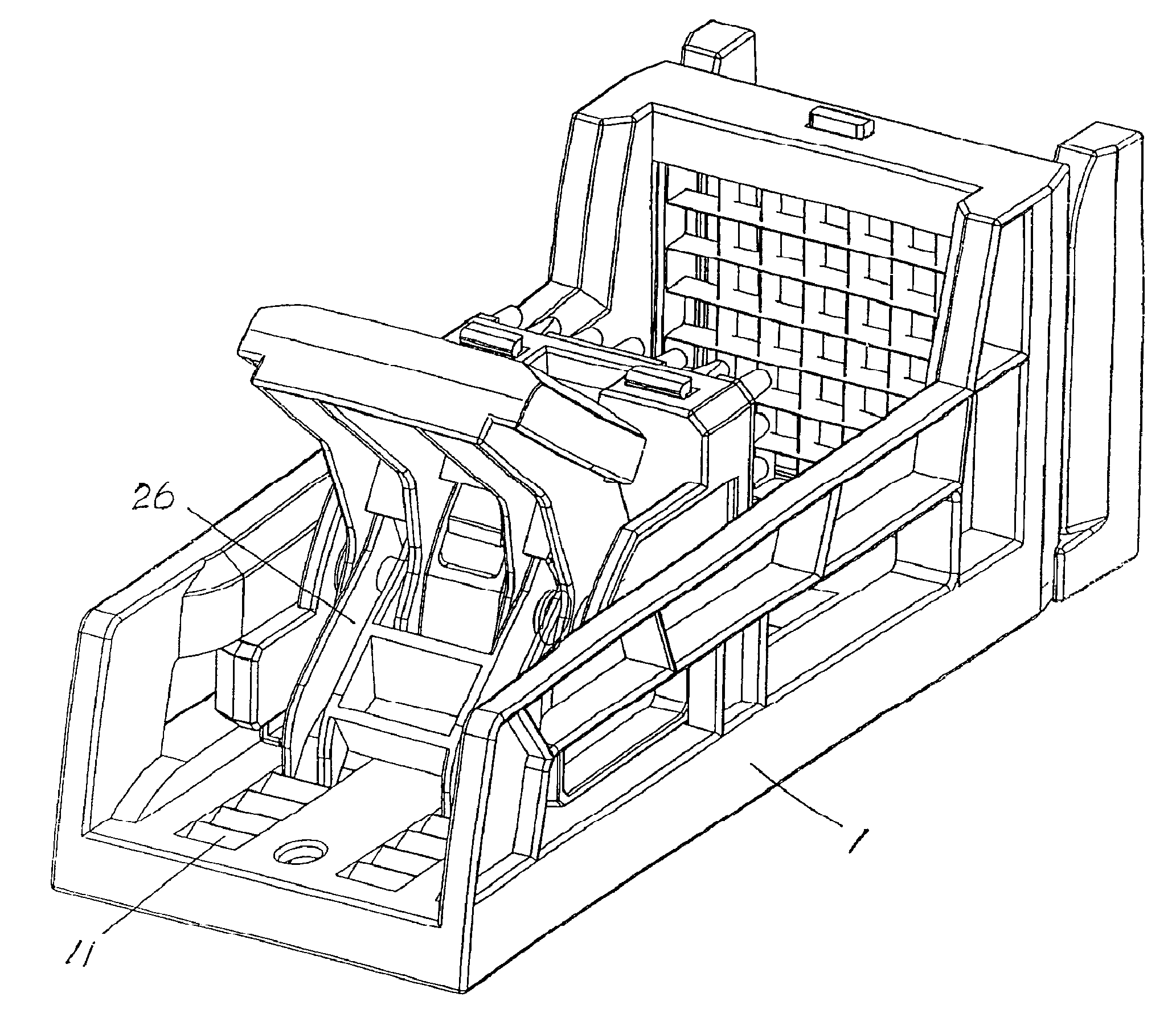
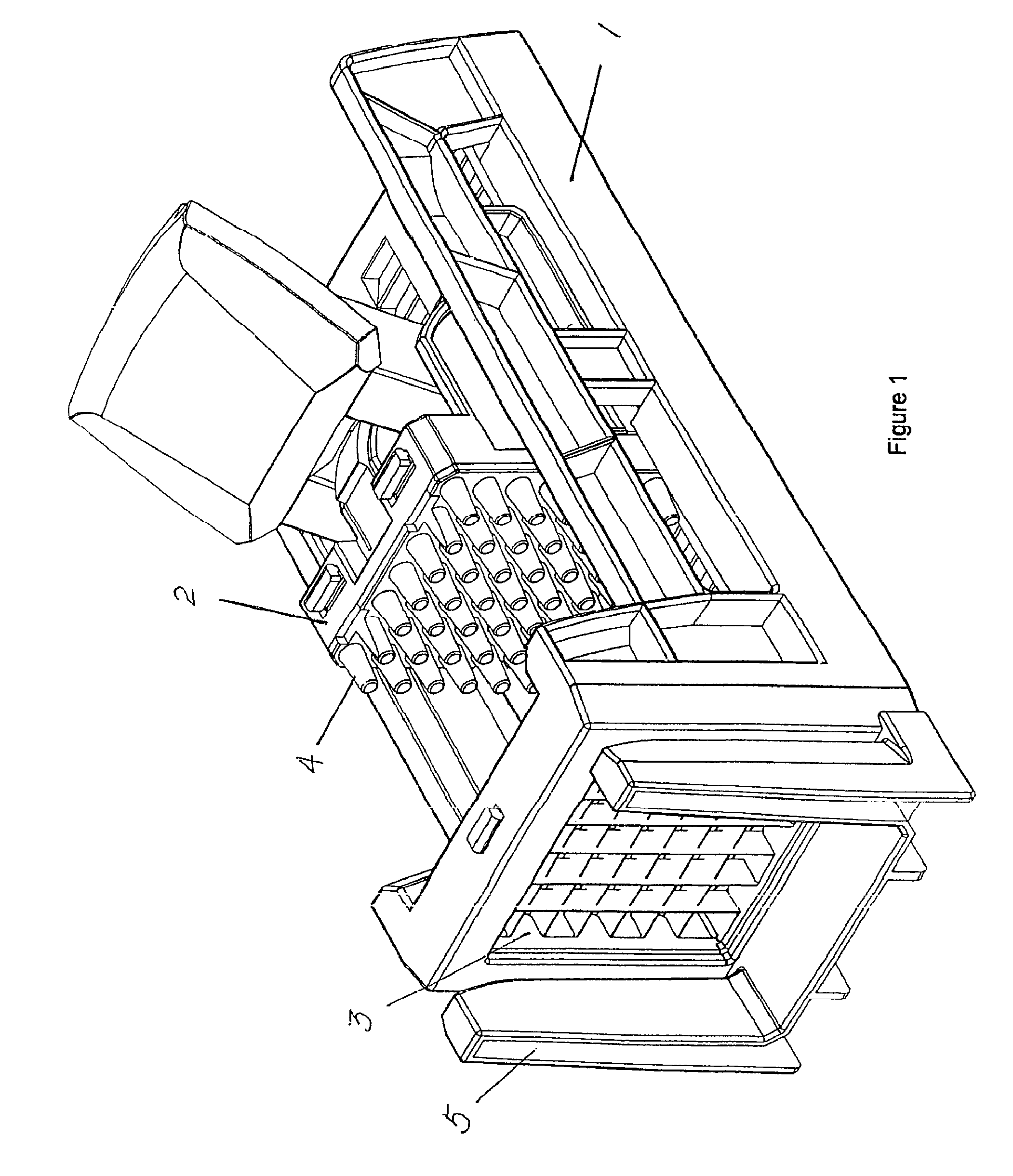
[0030]FIG. 1 shows an embodiment of the hand-operated cutting apparatus of the present invention, which comprises a main frame 1; a bracket 2 disposed in the main frame 1 and movable along the length of the latter; a cutter 3 provided in the front of the main frame 1 and a squeezer 4 provided on the front surface of the bracket 2 facing to the cutter 3.

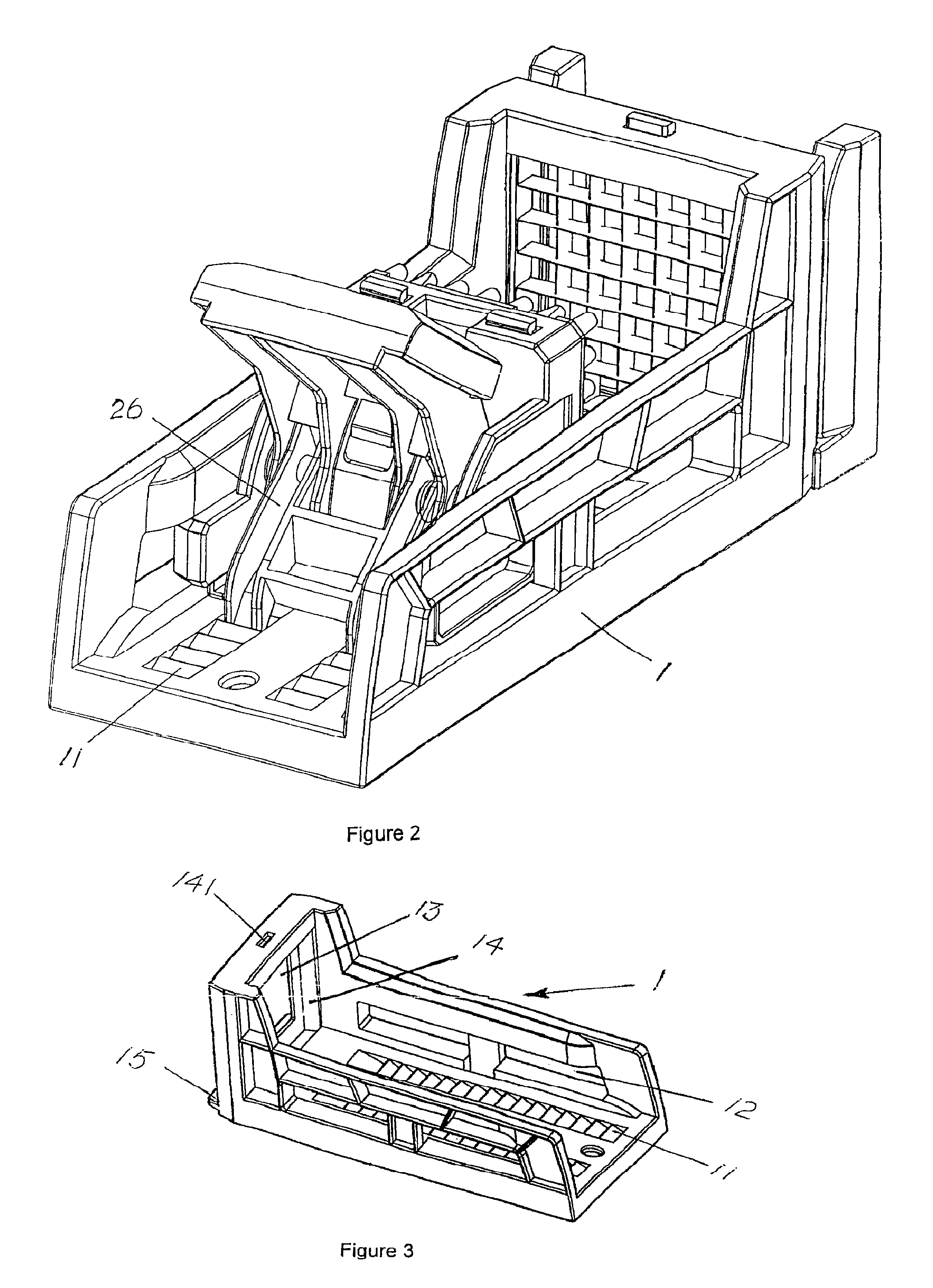
[0031]As shown in FIG. 3, the main frame 1 at least includes a front wall, a base wall and two side walls, and the top end and rear end thereof may be open. A rack 11 is formed on the upper surface of the base wall along the length of the main frame 1. On the inner surface of each side wall, a sliding groove 12 could be formed along the length of the main frame 1, to guide individual sliding blocks 214 formed on the bracket 2 (see FIG. 4). An opening 13 is formed in the front wall, and cutting blades 32 of the cutter 3 are located within the limit defined by the opening 13, to enable the objects to pass through the opening 13 after th...


PUM

PropertyMeasurementUnit
lengthaaaaaaaaaa
angleaaaaaaaaaa
included angleaaaaaaaaaa

Abstract

A hand-operated cutting apparatus including a main frame at least including a front wall, a base wall and two side walls, in which an opening is formed in the front wall, and a rack formed on an upper surface of the base wall along the length of the main frame, a bracket disposed between the side walls of the main frame and movable along the length of the main frame, a cutter provided in the front of the main frame and including a cutting blade located within the opening, and a squeezer attached to the front surface of the bracket facing to the cutter. The bracket includes a base, a handle pivotally provided on the base and a pusher arm pivotally provided on the handle, in which a lower end of the pusher arm is located between two teeth of the rack, and the pivot axis of the pusher arm on the handle departs from the pivot axis of the handle on the base towards the rear of the main frame.

Description

FIELD OF THE INVENTION[0001]The present invention relates to a cutting apparatus, and more particularly, to a hand-operated cutting apparatus for cutting objects into desired strips or particles.BACKGROUND OF THE INVENTION[0002]Traditionally, to cut objects, for example food, into desired strips or particles, a knife is needed. However, such kind of cutting operation is time-consuming and laborious, and the resultant shapes and sizes of the objects are not uniform.[0003]In order to overcome the above problems, some special cutting apparatuses have been proposed to cut objects into stripes. The operation of such special cutting apparatuses is as follows. The objects to be cut are placed between a fixed knife and a movable squeezer, and then the squeezer is pushed towards the knife to enable the cutting of the objects with the knife. Such kind of special cutting apparatuses may control the resultant shape of the objects, however, the operation of such apparatuses is still laborious.SU...

Claims


Application Information

Patent Timeline
Patent Type & Authority Patents(United States)
IPC IPC(8): B23D7/06B23D1/00B23D15/00G05G1/00B23D25/00
CPCB26D3/26B26D3/185B26D7/0608Y10T83/9411Y10T83/9495Y10T83/6664Y10T83/752Y10T83/662Y10T74/214
Inventor CHEUNG, YIU JOECHAN, CHUNG WAI STEPHEN
Owner COSSO INT
Why Eureka
Try Eureka