
Vehicle

a technology of pendulum and vehicle, applied in the field of vehicles, can solve the problems of one side spinning out, one of the wheels spinning out, and the balance of the load imposed on the left and right wheels will be lost, so as to prevent one of the wheels from spinning out, and inhibit the loss of lateral balance

Active Publication Date: 2014-02-04
HONDA MOTOR CO LTD
View PDF20 Cites 41 Cited by
  • Summary
  • Abstract
  • Description
  • Claims
  • Application Information

AI Technical Summary

Benefits of technology

The present invention offers an inverted pendulum type vehicle that prevents loss of lateral balance and spin-out of one of the wheels even when there is a load on the column. This is achieved by positioning the center point sliding of the column at the center point of the arc trajectory of the connecting part, which reduces the moment exerted on the base when the column slides. Overall, the vehicle ensures safe and stable driving.

Problems solved by technology

As a result, there is a risk that the balance of the load imposed on the left and right wheels will be lost, and that one of the wheels will spin out.
Consequently, when the passenger shifts his / her body weight either to the left or right side during travel and changes course, the load imposed on the wheel of one side is less than the load imposed on the wheel of the other side, and there is a risk that the wheel of that one side may spin out.

Method used


Image

  • Vehicle
  • Vehicle
  • Vehicle

Examples


embodiment 1

[0025]First, the configuration of the inverted pendulum type vehicle of a first embodiment is described.

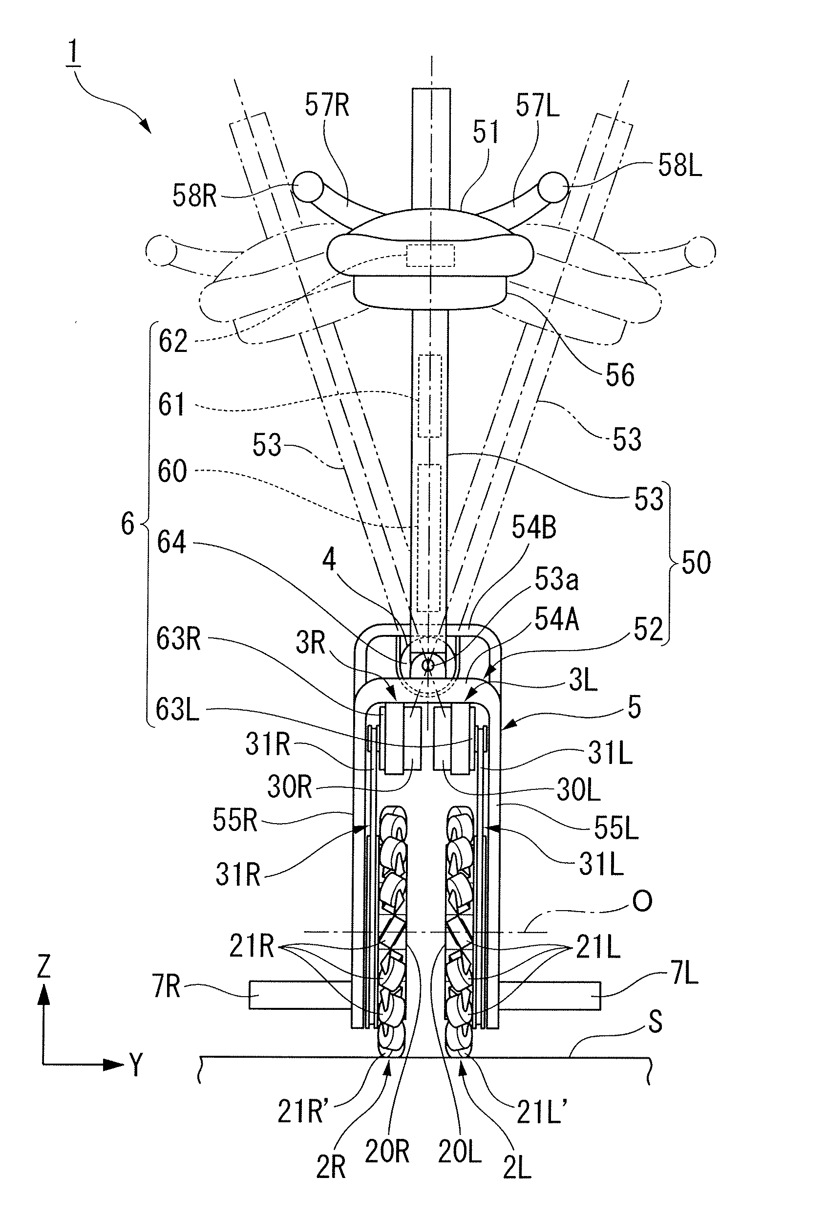
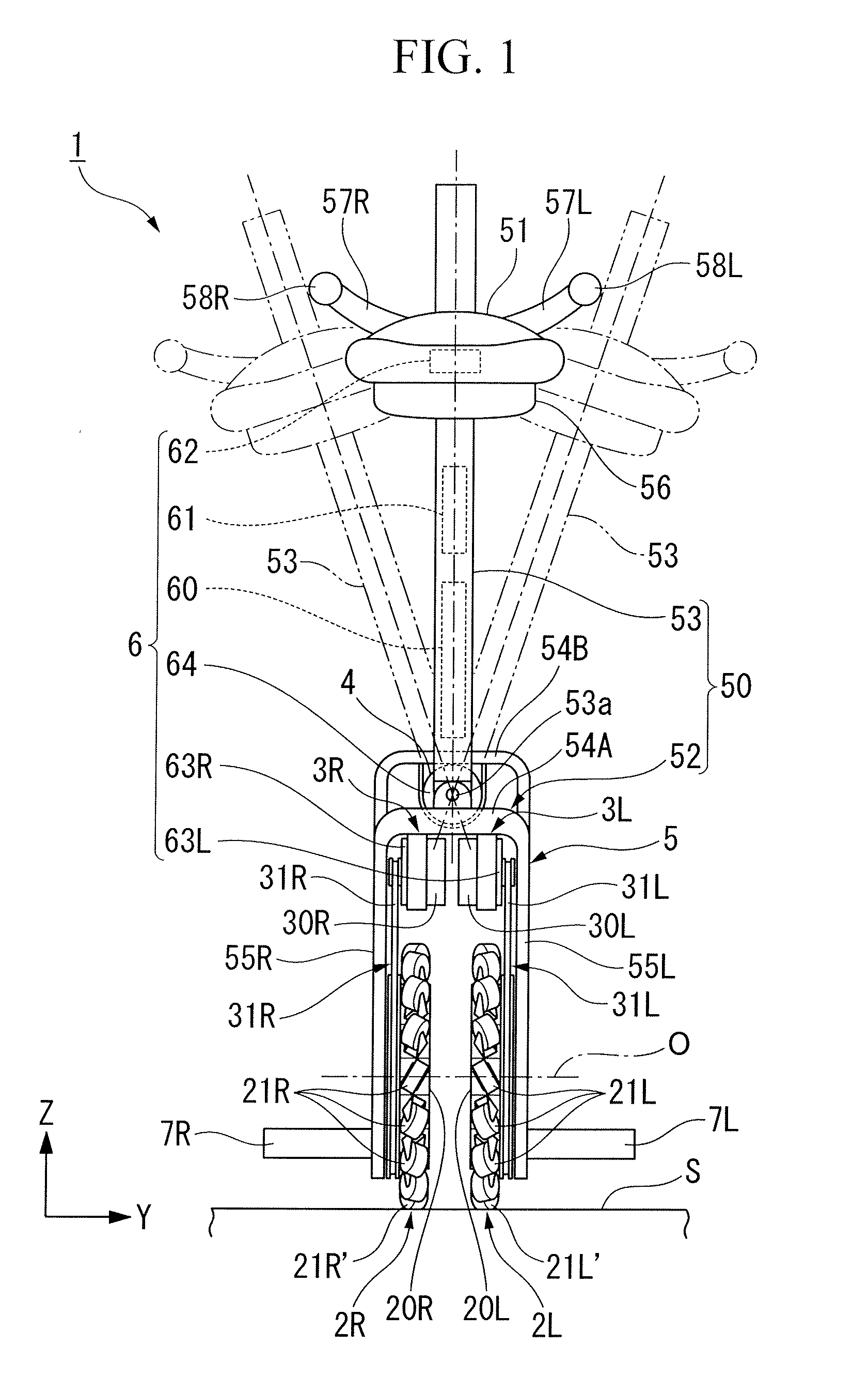
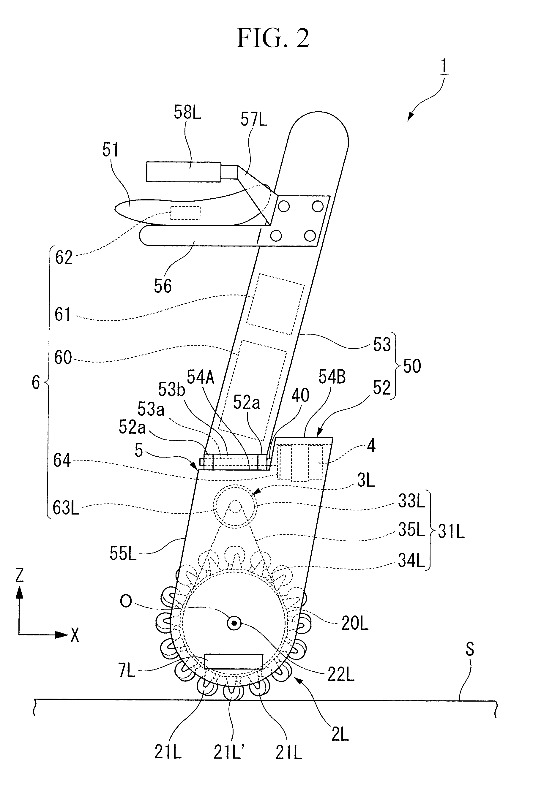
[0026]As shown in FIG. 1 and FIG. 2, a vehicle 1 of the present embodiment is an omnidirectional mobile vehicle capable of moving in all directions (all two-dimensional directions including the anteroposterior directions and lateral directions) on a road surface S, and is an electrically driven vehicle of inverted pendulum type regarding which a passenger mounted on the pertinent vehicle 1 conducts body weight movement in the desired direction and degree, thereby causing it to travel in the direction of body weight movement at a speed proportional to the degree of body weight movement. As for the schematic configuration of this vehicle 1, it is provided with a body 5, a pair of wheels 2R and 2L attached to the body 5 and arranged in parallel, drive mechanisms 3R and 3L which respectively impart the motivity that drives this pair of wheels 2R and 2L to the pertinent wheels 2R and 2...

embodiment 2

[0058]Next, the configuration of the inverted pendulum type vehicle of a second embodiment is described.

[0059]The vehicle 101 of the present embodiment is not provided with the actuator 4 of the vehicle 1 of the foregoing first embodiment, and the configuration of the connecting part of the base 52 and column 53 differs from that of the vehicle 1 of the aforementioned first embodiment, but the remaining configuration is identical to the configuration of the vehicle 1 of the aforementioned first embodiment. Accordingly, in the present embodiment, with respect to the configuration that is identical to the aforementioned first embodiment, the identical reference symbols are used, and explanation thereof is omitted.

[0060]As shown in FIG. 4 and FIG. 5, the column 53 of the vehicle 101 of the present embodiment is joined to the base 52 via a connecting part 153 that is capable of moving with an upward orientation along a convex arc trajectory around an axial line R that extends in a direc...


PUM


Abstract

An inverted pendulum type vehicle provided with a body, a pair of wheels and that is attached to the pertinent body and that is arranged in parallel, drive mechanisms and that separately rotate the pertinent pair of wheels and around wheel axes, and a control member that controls the drive mechanisms and, wherein: the body is provided with a base to which the pair of wheels and is attached, a column disposed upright from the base, and a load-supporting part that is attached to the column and that sustains a payload; the column is joined to the base via a shaft that extends in a non-parallel direction relative to the wheel axes, and is provided so as to be capable of sliding around the shaft; and the shaft is provided with an actuator which imparts torque to the column that slides around the shaft with an orientation that is the reverse of the sliding direction of the column.

Description

FIELD OF THE INVENTION[0001]The present invention relates to an inverted pendulum type vehicle.[0002]Priority is claimed on Japanese Patent Application No. 2009-219709, filed Sep. 24, 2009. The content is incorporated herein by reference.DESCRIPTION OF THE RELATED ART[0003]In recent years, numerous inverted pendulum type vehicles have been proposed which can be maneuvered by intuitive manipulations involving weight shifts of the passenger. Previously, as this type of inverted pendulum type vehicle, vehicles have been offered which are provided with a pair of wheels that are laterally arranged in parallel, drive mechanisms that rotationally drive this pair of wheels, a control member that controls the drive mechanisms, and a body to which the pair of wheels is attached, as recorded, for example, in the U.S. Pat. No. 7,275,607, PCT International Publication WO2008 / 132778, and PCT International Publication WO2008 / 132779. The aforementioned body is provided with a base to which the whee...

Claims


Application Information

Patent Timeline
Patent Type & Authority Patents(United States)
IPC IPC(8): B62K3/00
CPCB62K1/00B62K3/007B62K11/007
Inventor TAKENAKA, TORU
Owner HONDA MOTOR CO LTD
Learn More