Anti-sway trailer hitch and method

Active Publication Date: 2014-02-04
CAMCO MFG LLC
View PDF25 Cites 11 Cited by
  • Summary
  • Abstract
  • Description
  • Claims
  • Application Information

AI Technical Summary

Benefits of technology

[0009]It is a further objective of the present invention to provide a hitch assembly with a cap that can be tightened with a wrench to permit a user to incrementally control the permitted degree of sway in a trailer.
[0010]It is still a further objective of the present invention to provide an anti-sway trailer hitch that uses a pair of plates which have plateaus of different slopes to control the range of motion allowed by a trunnion which is inserted into a channel in the ball mount housing.
[0011]I

Problems solved by technology

This problem has the potential to be very dangerous as it may cause the driver of the tow vehicle to lose control of the trailer and the vehicle during operation.
Also known as “locking” the trailer to the tow vehicle, such a strategy avoids the fishtailing issue but creates new challenges as well.
One problem is that when a heavily loaded trailer and tow vehicle are locked together, the linear force exerted by the trailer entering a turn ca

Method used


Image

  • Anti-sway trailer hitch and method
  • Anti-sway trailer hitch and method
  • Anti-sway trailer hitch and method

Examples


Example

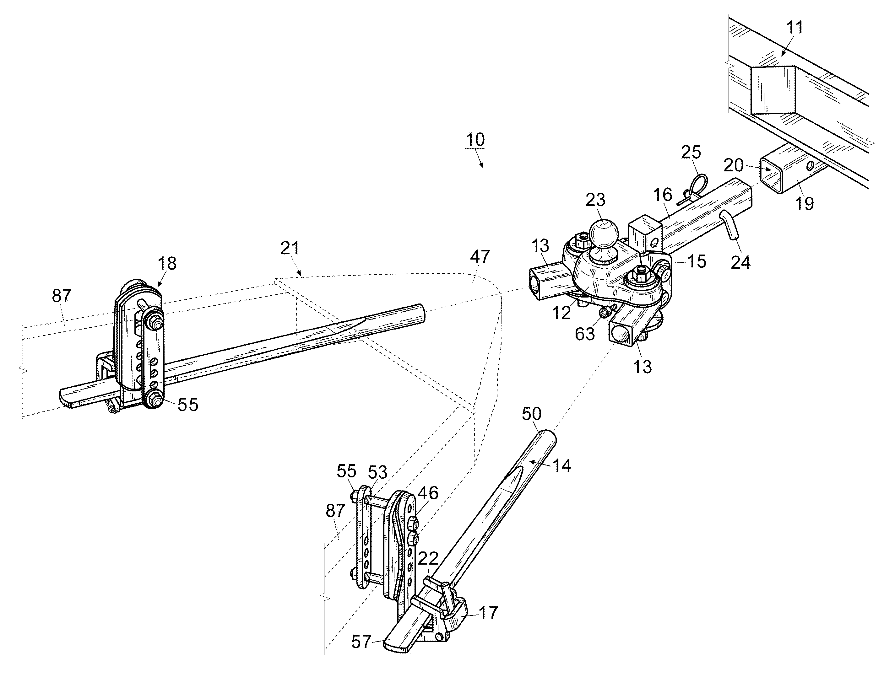
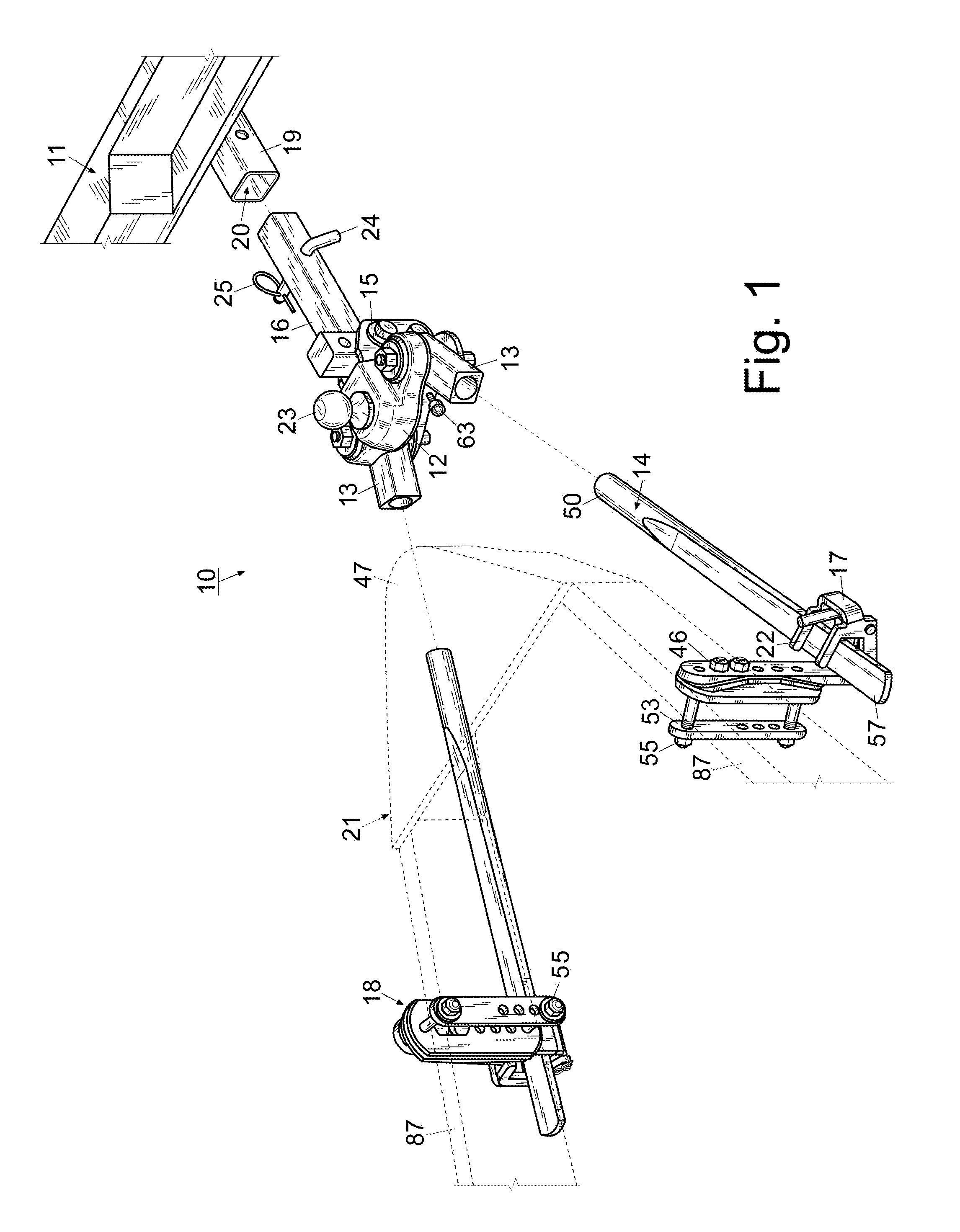
[0027]For a better understanding of the invention and its operation, turning now to the drawings, FIG. 1 shows an elevated side perspective view of a schematic representation of anti-sway trailer hitch 10 prior to engagement with trailer 21 and tow vehicle 11 as known in the art. Hitch 10 is affixed to tow vehicle 11 by placing shank 16 into receptacle 20 of tow hitch 19 and securing shank 16 therein with hitch pin 24 and cotter pin 25 (FIG. 2) as is conventional. Thereafter, trailer 21 is raised above hitch ball 23 whereby trailer tongue 47 is lowered until hitch ball 23 is engaged and trailer tongue 47 is locked into place as is conventional. Spring bars 14 are then inserted into trunnions 13 of hitch 10 and thereafter secured to trailer 11 by attachment of retainers 17 (FIG. 6) and couplings 18 described in more detail below. Once connected and secure tow vehicle 11 may then commence towing trailer 21.

[0028]Preferred weight distributing anti-sway hitch 10 includes forged two-piec...


PUM


Abstract

An anti-sway hitch having a ball mount housing which defines a channel and a trunnion pivotally positioned within the channel. The hitch also has a spring, a first engagement member, and a second engagement member with the spring mounted on the first member within the ball mount housing and the first member engaging the second member. The hitch further includes a post positioned within the ball mount housing and the engagement members positioned on the post wherein rotation of the trunnion causes corresponding rotation of the post and the first member. A method of towing a trailer with an anti-sway hitch is also provided.

Description

FIELD OF THE INVENTION[0001]The invention herein pertains to weight distributing trailer hitches generally and particularly pertains to an anti-sway trailer hitch with an opposing pair of engagement members to control trailer sway and an improved loading retainer.DESCRIPTION OF THE PRIOR ART AND OBJECTIVES OF THE INVENTION[0002]Typically, a trailer is connected to a tow vehicle with a ball and socket coupling located at the rear of the tow vehicle. For example, the tow vehicle is fitted with a hitch ball positioned at the end of the shank mounted on the tow vehicle which projects either upwardly or outwardly from the tow vehicle bumper, while the trailer has a socket coupler on a forward projecting tongue. The socket is designed to fit over and close around the ball hitch to secure the trailer to the tow vehicle. This arrangement allows the tow vehicle to turn relative to the trailer, but it also allows the trailer to sway laterally (i.e. left or right) relative to the tow vehicle. ...

Claims


Application Information

Patent Timeline
IPC IPC(8): B60D1/30
CPCB60D1/30B60D1/07B60D1/06
Inventor ANGEL, BRUCE, A.
Owner CAMCO MFG LLC
Why Eureka
Try Eureka