Self-retaining suture with variable dimension filament and method

a self-retaining suture and variable dimension technology, applied in the field of self-retaining systems for surgical procedures, can solve the problems that the creation or deployment of retainer features of self-retaining sutures may be difficult to achieve, and achieve the effect of reducing the core cross-section of filament and minimizing the impact of retainer formation on the final tensile strength of sutures

Active Publication Date: 2014-02-04
ETHICON INC
View PDF969 Cites 51 Cited by
  • Summary
  • Abstract
  • Description
  • Claims
  • Application Information

AI Technical Summary

Benefits of technology

[0009]Thus, it would be desirable to provide improved self-retaining sutures which have enhanced ability to anchor into the surrounding tissue, enhanced tissue holding capabilities, enhanced maximum load, and enhanced clinical performance.
[0010]It would further be desirable to provide improved methods for making self-retaining sutures that yield retainers which can be more readily created, elevated and deployed.
[0011]In accordance with the foregoing background and the limitations of the prior art, the present invention provides, improved self-retaining sutures which have enhanced ability to anchor into the surrounding tissue, enhanced tissue holding capabilities, enhanced maximum load, and enhanced clinical performance and methods for making such self-retaining sutures.
[0014]In accordance with another aspect, the present invention provides sutures including a variable-dimension filament which has additional material at locations where retainers are formed such that the forming of retainers does not reduce the core cross-section of the filament.
[0015]In accordance with another aspect, the present invention provides sutures including a variable-dimension filament which forms a different distribution of material at some locations compared to other locations and where retainers are formed such that the retainers make use of the differently distributed material so as to minimize the impact of retainer formation upon the final tensile strength of the suture.

Problems solved by technology

Furthermore, the creation and or deployment of retainer features of self-retaining sutures may be difficult to achieve.

Method used


Image

  • Self-retaining suture with variable dimension filament and method
  • Self-retaining suture with variable dimension filament and method
  • Self-retaining suture with variable dimension filament and method

Examples


second embodiment

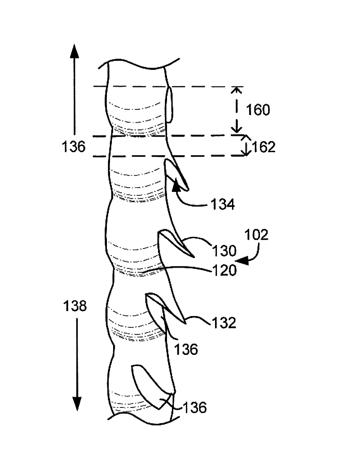
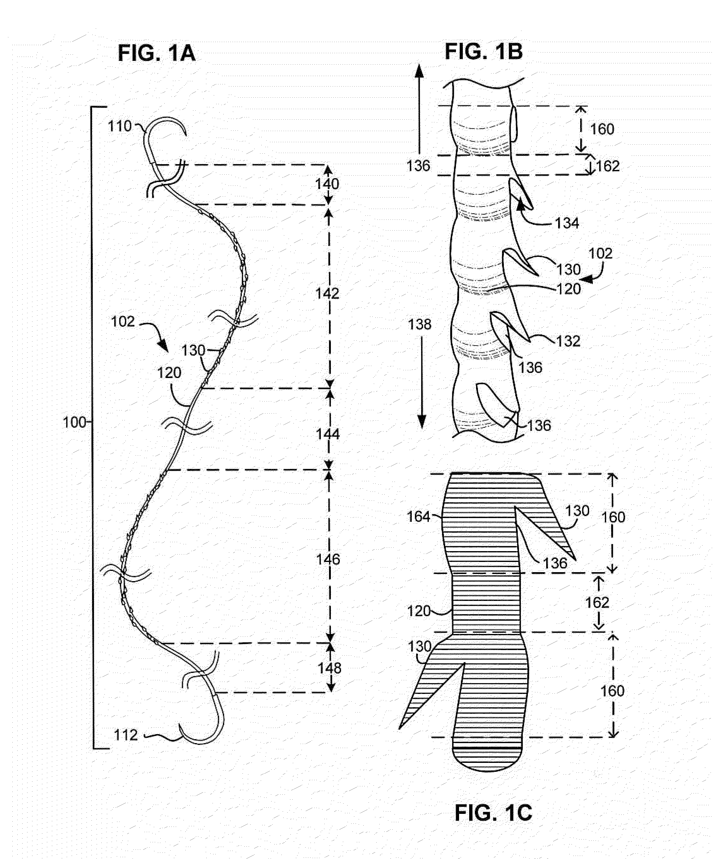
[0076]FIG. 4C illustrates a self-retaining suture 430 according to an embodiment of the present invention. In self-retaining suture 430 of FIG. 4C, retainers 432 are cut in a filament 434 which has a sinusoidal variation in the distribution of material. In the suture 430 of FIG. 4C the cross-sectional area varies along the length of the filament. Retainers 432 are cut into the filament 434 so as to utilize the regions of additional material 436. After the retainers 432 are cut, the minimum cross-section of the filament remaining is significantly larger than for the uniform filament of FIG. 4A. The minimum cross-section will be larger even where the volume of material in the filament is equivalent. Thus, the configuration of FIG. 4C results in a larger minimum cross-section after retainer cutting for the same volume material. This results in a higher tensile strength for a given suture size than would be possible with a uniform filament. Although a sinusoidal distribution has been il...

third embodiment

[0077]FIG. 4D illustrates a self-retaining suture 440 according to an embodiment of the present invention. In self-retaining suture 440 of FIG. 4D, retainers 442 are cut in a filament 444 which has a non-sinusoidal variation in the distribution of material. Retainers 442 are cut into the filament so as to utilize the regions of additional material 446. After the retainers 442 are cut, the minimum cross-section of the filament remaining is significantly larger than for the uniform filament of FIG. 4A. The minimum cross-section will be larger even where the volume of material in the filament is equivalent. Thus, the configuration of FIG. 4D results in a larger minimum cross-section after retainer cutting for the same volume material. This results in a higher tensile strength for a given suture size than would be possible with a uniform filament.

fourth embodiment

[0078]FIG. 4E illustrates a self-retaining suture 450 according to an embodiment of the present invention. In self-retaining suture 450 of FIG. 4E, retainers 452 are formed by localized melting of filament 454 which has a sinusoidal variation in the distribution of material. Retainers 452 are formed by melting the filament and the melted filament material is drawn out by tool 458. Forming the retainers 452 in this manner requires material and consequently the amount of material remaining in the filament is reduced surrounding the retainers 452. However, the retainers 452 are formed in the regions 456 where extra material having extra material. Thus, even after the retainers 452 are formed, the minimum cross-section of the filament remaining is as large as or larger than the cross-section of the filament in the inter-retainer regions. Thus the configuration of FIG. 4E results in a larger minimum cross-section after retainers 452 are formed for the same volume of material. This result...


PUM

PropertyMeasurementUnit
diameteraaaaaaaaaa
sizeaaaaaaaaaa
lengthaaaaaaaaaa

Abstract

A self-retaining suture comprises a variable-dimension filament which varies in size and / or shape along the length of the filament. The variation in size and / or shape results in a variation in the distribution of filament material from one region of the filament to the next. The filament has retainers formed in the surface such that the filament can engage and retain tissue. The retainers are formed in a manner that makes use of regions of the filament where additional material is distributed. The resulting self-retaining suture has a greater minimum cross-section than would be created using an equivalent uniform filament. The resulting self-retaining suture consequently has a greater tensile strength. Methods for manufacturing the filament and retainers are also described.

Description

FIELD OF INVENTION[0001]The present invention relates generally to self-retaining systems for surgical procedures, methods of manufacturing self-retaining systems for surgical procedures, and uses thereof.BACKGROUND OF THE INVENTION[0002]Wound closure devices such as sutures, staples and tacks have been widely used in superficial and deep surgical procedures in humans and animals for closing wounds, repairing traumatic injuries or defects, joining tissues together (bringing severed tissues into approximation, closing an anatomical space, affixing single or multiple tissue layers together, creating an anastomosis between two hollow / luminal structures, adjoining tissues, attaching or reattaching tissues to their proper anatomical location), attaching foreign elements to tissues (affixing medical implants, devices, prostheses and other functional or supportive devices), and for repositioning tissues to new anatomical locations (repairs, tissue elevations, tissue grafting and related pr...

Claims


Application Information

Patent Timeline
Patent Type & Authority Patents(United States)
IPC IPC(8): A61B17/04
CPCA61B17/04A61B17/06166A61B2017/00526A61B2017/06176D01D5/12A61B2017/00849D01D5/20D06M10/00D01D5/22A61B2017/00893
Inventor GORALTCHOUK, ALEXEINAIMAGON, ALEXANDERCUMMINGS, GERALD F.DRUBETSKY, LEVHERRMANN, ROBERT A.
Owner ETHICON INC
Why Eureka
Try Eureka