Supercharge Your Innovation With Domain-Expert AI Agents!

Developing apparatus

a technology of developing apparatus and developing electrode, which is applied in the direction of electrographic process apparatus, instruments, optics, etc., can solve the problems of affecting the detection accuracy of toner density, and displaying a different density than the actual toner density, etc., to suppress the deterioration of stirring properties, and suppress the deterioration of density detection accuracy

Active Publication Date: 2014-02-04
CANON KK
View PDF16 Cites 0 Cited by
  • Summary
  • Abstract
  • Description
  • Claims
  • Application Information

AI Technical Summary

Benefits of technology

The present invention is about improving the accuracy of detecting the density of toner in a developing apparatus. It does this by preventing the toner from sticking to the sensor, which can cause errors in the detection. The invention also maintains the stirring properties of the toner, which helps to keep it mixed properly.

Problems solved by technology

However, there are the following problems when controlling the toner density using a magnetic permeability sensor.
As a consequence, the arrangement location of the toner density sensor can be limited.
A toner that is susceptible to retention like this may show a different density from the actual toner density because the toner cannot be easily replaced.
Thus, there is the problem that the toner density cannot be detected with high accuracy.
However, with a configuration such as that in Japanese Patent No. 3434118, there is the following problem.
The fact that the carrying rate of the developer decreases means that the developer which is present in the portion opposing the sensor face tends to stop at the same location, so that developer replacement in the portion opposing the sensor face becomes more difficult.
Consequently, it becomes impossible to accurately follow the changes in the developer density in the developing apparatus.
Further, if the developer is retained in the portion opposing the sensor, a surface of the developer opposing the sensor tends to be unstable.
Therefore, if the surface of the developer fluctuates, height density at a detecting position of the sensor fluctuates, which may cause false detection.
Thus, although providing a rib on the shaft of the developer stirring / carrying member has an effect in improving stirring properties, it has not been sufficient in terms of its effect on developer replacement.
On the other hand, while the carrying rate in the shaft direction could be increased for all areas, as a result, this would deteriorate the stirring properties of the developer in the developing apparatus.
Thus, a problem would arise in terms of stirring (i.e., it becomes more difficult for the replenishment toner to mix with the developer, so that the toner density in the developing apparatus would not be uniform).

Method used


Image

  • Developing apparatus
  • Developing apparatus
  • Developing apparatus

Examples


Embodiment Construction

[0027]Various exemplary embodiments, features, and aspects of the invention will be described in detail below with reference to the drawings.

[0028]Before describing the developing apparatus according to the present invention, first, the outline of a representative electrophotographic image forming apparatus illustrated in FIG. 1 will be described as an example of the image forming apparatus on which the developing apparatus is mounted.

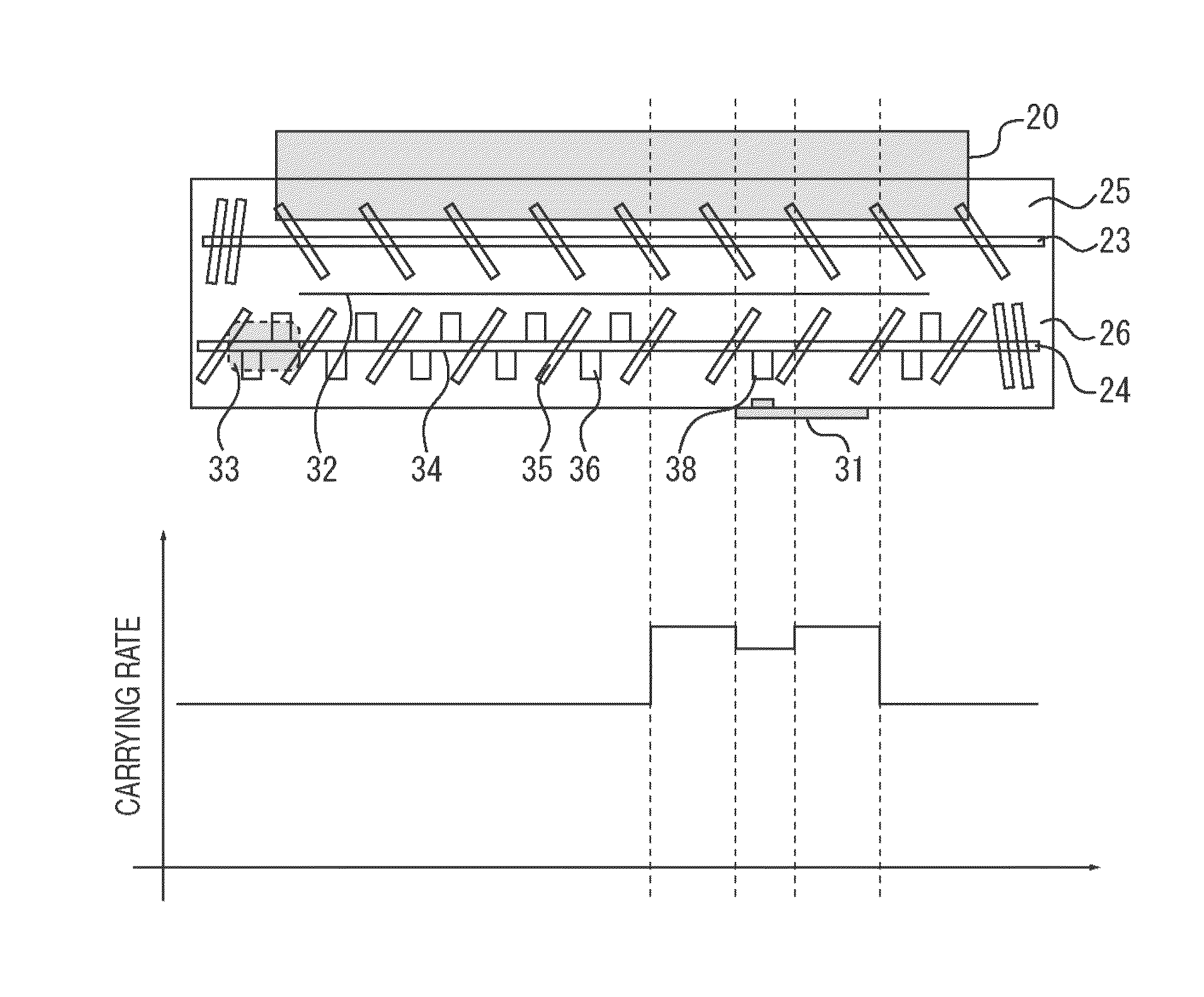
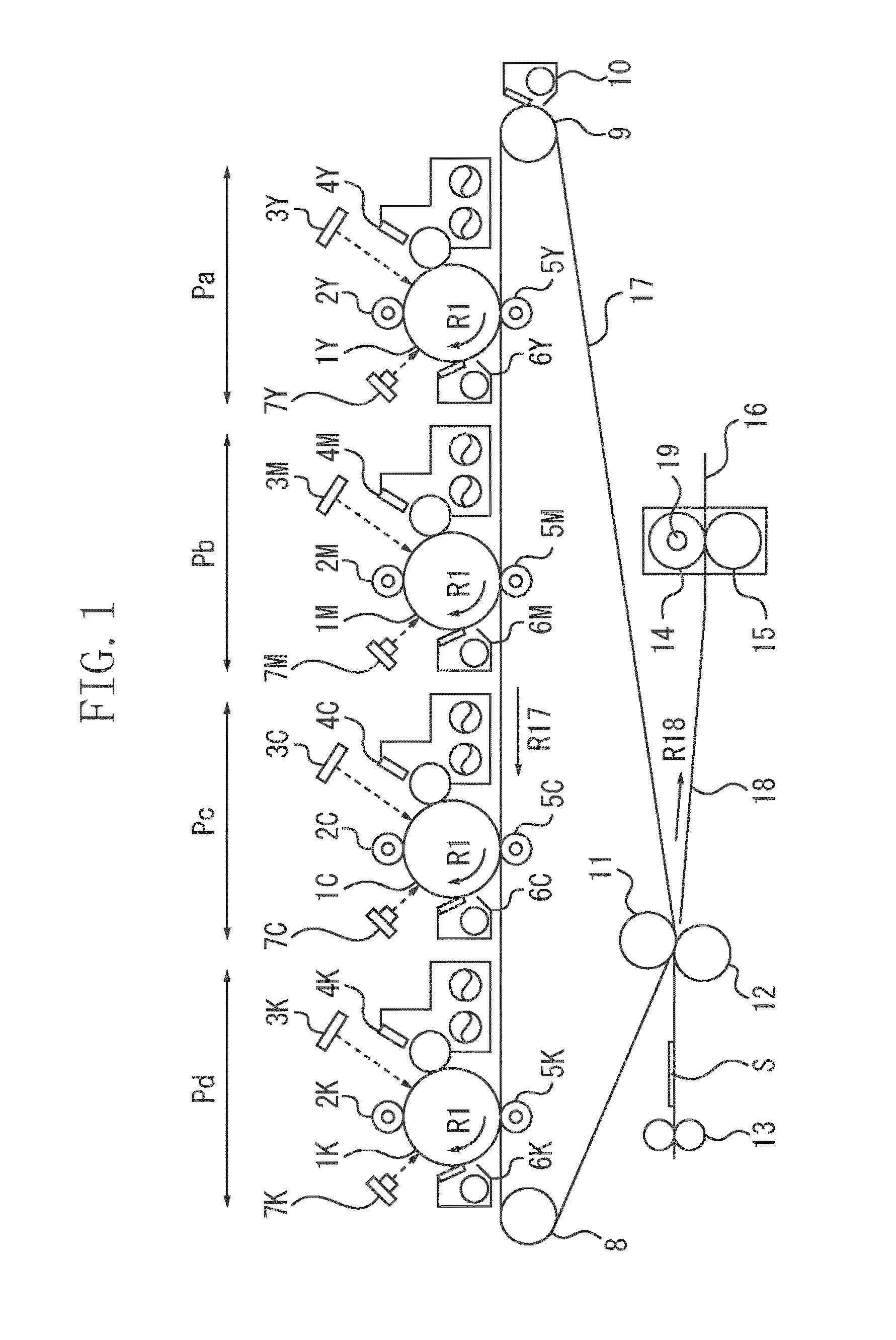
[0029]The image forming apparatus illustrated in FIG. 1 is a full color electrophotographic image forming apparatus for four colors having four image forming units. FIG. 1 is a longitudinal sectional view schematically illustrating the general configuration of such an image forming apparatus. The image forming apparatus illustrated in FIG. 1 has four image forming units (image forming stations) Pa, Pb, Pc, and Pd arranged from an upstream side to a downstream side along a rotation direction (arrow R17 direction) of an intermediate transfer belt 17 acti...


PUM


Abstract

In the present invention, for a developing apparatus provided with a sensor for detecting the toner density of a developer, retention of the developer near the sensor face can be suppressed by increasing the force with which the developer present near the sensor face is carried in a shaft direction of a stirring / carrying member.

Description

BACKGROUND OF THE INVENTION[0001]1. Field of the Invention[0002]The present invention relates to a developing apparatus which uses a two-component developer to develop an electrostatic latent image formed on an image carrier in an image forming apparatus, such as a copying machine, a printer, a recorded image display device, and a facsimile machine, using an electrophotographic method, an electrostatic recording method or the like.[0003]2. Description of the Related Art[0004]For a developing apparatus included in an image forming apparatus, a one-component developer having a non-magnetic toner or a magnetic toner as a main component, or a two-component developer having a non-magnetic toner and a magnetic carrier as main components, is used. Especially for a color image forming apparatus which forms a full color or a multi-color image by electrophotography, from the perspective of the tint and the like of the image, most developing apparatuses use a two-component developer.[0005]Cons...

Claims


Application Information

Patent Timeline
Patent Type & Authority Patents(United States)
IPC IPC(8): G03G15/00
CPCG03G15/0829G03G15/0893G03G15/0853
Inventor KAKUBARI, KOUICHI
Owner CANON KK
Features
  • R&D
  • Intellectual Property
  • Life Sciences
  • Materials
  • Tech Scout
  • Unparalleled Data Quality
  • Higher Quality Content
  • 60% Fewer Hallucinations
Learn More