
Lighting device

a technology of lighting device and el lamp, which is applied in the direction of mobile visual advertising, identification means, instruments, etc., can solve the problems of difficult to tell by looking at the el lamp whether or not the el lamp is energized, and achieve the effects of simple battery replacement operation, low maintenance, and convenient us

Active Publication Date: 2014-02-11
POWERDECAL HLDG
View PDF5 Cites 37 Cited by
  • Summary
  • Abstract
  • Description
  • Claims
  • Application Information

AI Technical Summary

Benefits of technology

The light film device provides highly visible and dynamic graphic displays that are user-friendly, energy-efficient, and compliant with regulations, improving safety and marketability by ensuring visibility in adverse conditions while minimizing maintenance and operational costs.

Problems solved by technology

Illumination provided by the EL lamp may be less than the illumination of background brightness, making it difficult to tell by looking at the EL lamp whether or not the EL lamp is energized.

Method used


Image

  • Lighting device
  • Lighting device
  • Lighting device

Examples


Embodiment Construction

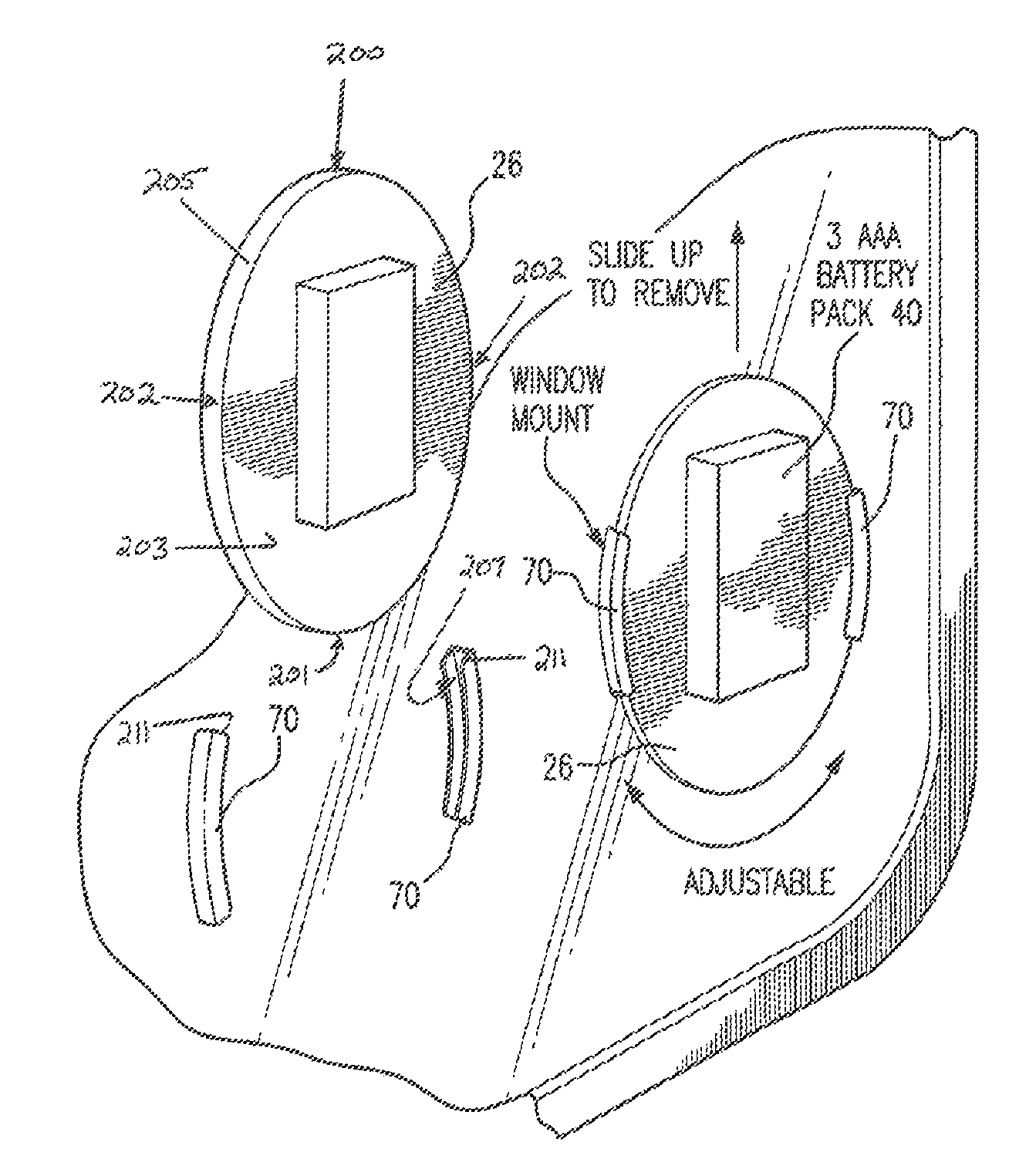
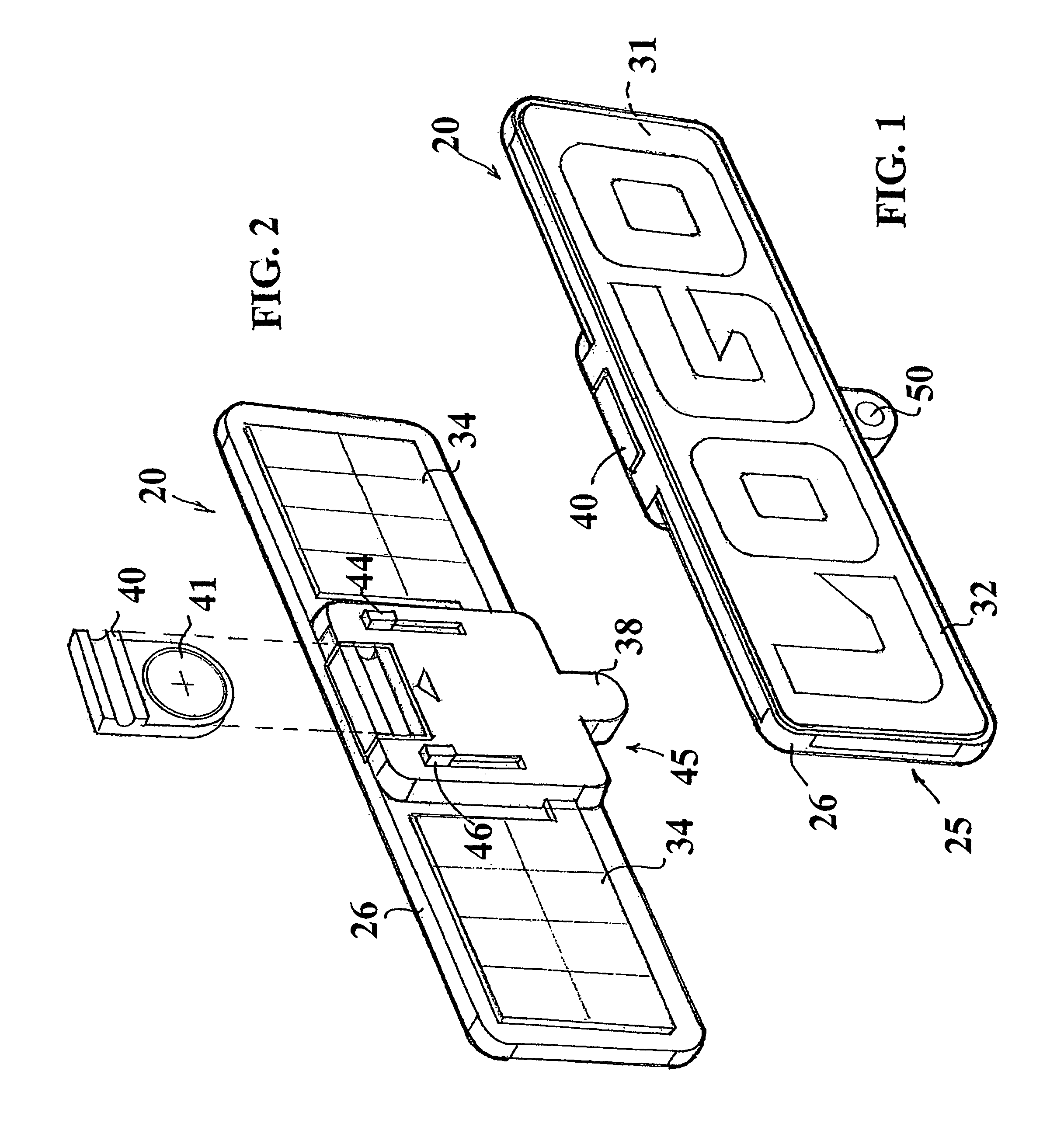
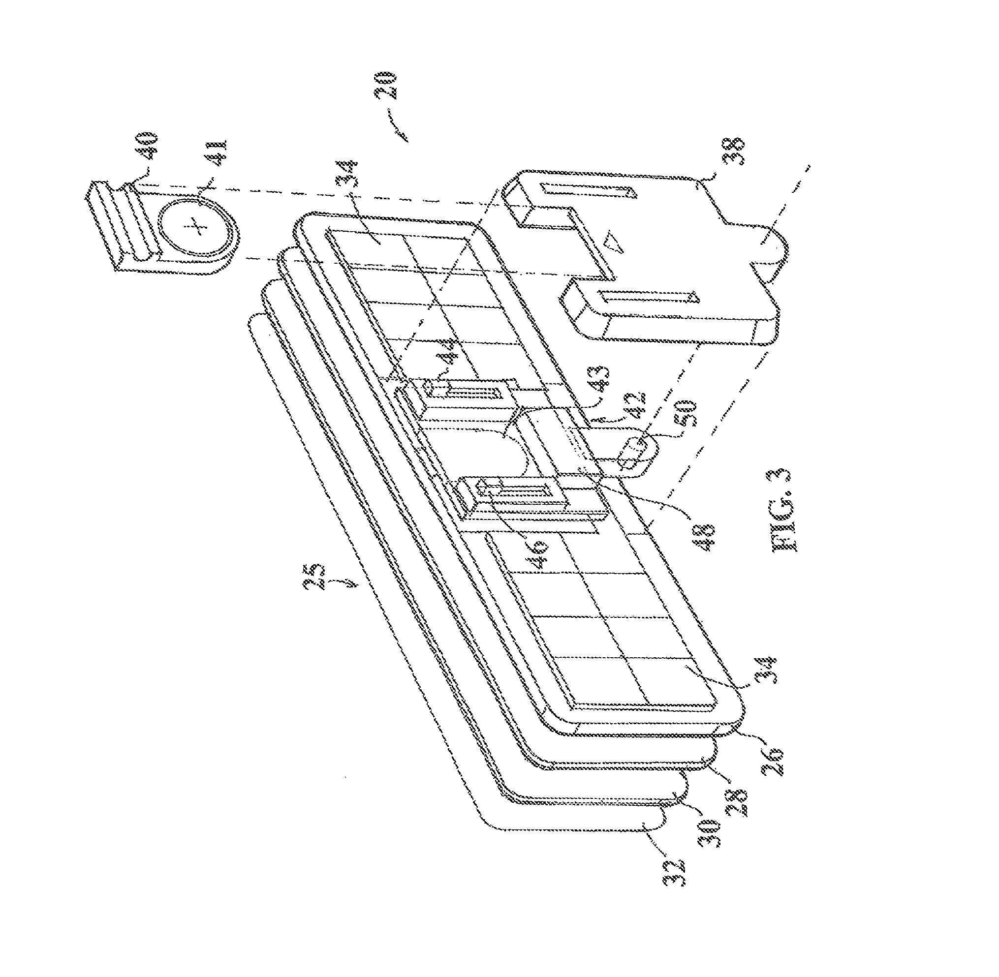
[0132]This invention provides a light film device including a light film component, a control module and in certain embodiments a solar power unit and / or a battery. FIGS. 1-19 show a light film device, according to certain embodiments of this invention. The light film device can be mounted with respect to a window, such as vehicle window 100 shown in FIG. 17, to display desired graphics for marketing applications, safety applications and / or emergency situations, for example. The light film device of this invention can provide highly visible graphics that other motorists and / or pedestrians or bystanders will be able to see in adverse weather conditions and / or adverse driving conditions, for example. The light film device of this invention can be used for a variety of applications including, but not limited to, safety signals, public service symbols, such as the Department of Transportation, the Military, the National Guard, the Police and the Fire Department logos or plaques, constru...


PUM


Abstract

A light film apparatus having an illuminated graphics panel with at least two segments that can be individually powered. A controller manages a power which is delivered from a power supply to each of the segments, so that each of the segments is either powered on, powered off or powered to an intermediate level. With the independent control of power to the different segments, it is possible to create a three-dimensional appearance of a moving image from a generally two-dimensional panel arrangement. A housing can be mounted so that the graphics panel abuts or is closely mounted to a mounting surface.

Description

[0001]This Provisional U.S. Patent Application is related to and a continuation-in-part patent application of U.S. patent application Ser. No. 11 / 803,722, filed 15 May 2007, to which priority is claimed, which is a continuation-in-part patent application of U.S. patent application Ser. No. 11 / 444,174, filed 31 May 2006, to which priority is claimed, which is a continuation-in-part patent application of U.S. patent application Ser. No. 11 / 259,909, filed 27 Oct. 2005, to which priority is claimed, and this Patent Application also claims priority to U.S. Provisional Patent Application Ser. No. 60 / 623,754, filed 29 Oct. 2004, and to U.S. Provisional Patent Application Ser. No. 60 / 724,476, filed 7 Oct. 2005, and the entire teachings and the full disclosure of each of the above-identified U.S. Patent Applications and U.S. Provisional Patent Applications are by reference hereto incorporated into and made a part of this specification and this Provisional U.S. Patent Application.BACKGROUND O...

Claims


Application Information

Patent Timeline
Patent Type & Authority Patents(United States)
IPC IPC(8): G09F13/18A47G1/17G09F21/04G09F13/22G09F13/04
CPCG09F9/33G09F13/22G09F13/04G09F21/04H05B37/029H05B37/0218H05B37/0227H05B47/155H05B47/11H05B47/115H05B44/00H05B47/105
Inventor PODD, GEORGE, O.
Owner POWERDECAL HLDG
Learn More