
Crash module for a rail vehicle

a technology for rail vehicles and crash modules, which is applied to buffer cars, railway bodies, underframes, etc., can solve the problems of increasing the risk of collision with an obstacle other than another rail vehicle, providing no deformation conditions suitable for absorbing transverse collisions, and unable to meet longitudinal collision requirements. , to achieve the effect of easy assembly, easy replacement, and fast repair

Inactive Publication Date: 2014-02-11
SIEMENS MOBILITY AUSTRIA GMBH
View PDF22 Cites 2 Cited by
  • Summary
  • Abstract
  • Description
  • Claims
  • Application Information

AI Technical Summary

Benefits of technology

[0016]A further essential advantage of the present invention is that thanks to the use of the crash module described here rail vehicles can be repaired very quickly, easily and economically in most cases (provided the impact energy was not too great) after transverse collisions, since the crash module absorbs the impact energy and consequently the car body structure is protected from damage. In known crash modules, in contrast, transverse collisions lead in most cases to damage to the car body structure.
[0017]In cases where impact energies are only small it is even possible to repair the crash module by replacement of individual affected components of the crash module.
[0018]It is furthermore particularly advantageous to configure the crash module from a plurality of crash elements (typically one each to the left and right of the vehicle longitudinal axis), a rear connecting plate, a front connecting plate and one or two transverse profiled elements. In such a way an easy-to-assemble and easily replaceable crash module can be built. In this case the car body is equipped with means for accommodating such a crash module (e.g. connecting plate with fixed connection points, called an “interface”) and the crash element is secured thereto either detachably (for example by means of screwed connections) or permanently (e.g. by welding).
[0019]In an embodiment variant of the invention it is provided to equip a crash module with means for preventing climbing (anti-climber).
[0020]In a further preferred embodiment variant of the invention it is provided to design the crash module as a multi-stage structure, the first stage being implemented with reversible buffer elements which can absorb small impact energies without a plastic deformation (either of the buffer elements or of the crash elements) occurring in the process.

Problems solved by technology

A further problem presents itself in the case of rail vehicles for which there exists an increased risk of a collision with an obstacle other than another rail vehicle (in particular streetcars).
Conventional crash modules designed to handle longitudinal collisions are often unable to absorb said transverse loading satisfactorily, since said crash modules are in this case subject to a bending and shearing stress under which the affected crash element will buckle sideways in the absence of any precautionary measures to provide transverse support.
Although the crash module disclosed therein prevents the overriding of the rail vehicles, it provides no deformation conditions suitable for absorbing transverse collisions.
A corresponding configuration of the known crash elements in a manner that enables them to handle both longitudinal and transverse collisions equally well would lead to extremely costly, complicated and heavy crash elements which are not suitable for use on rail vehicles.

Method used


Image

  • Crash module for a rail vehicle
  • Crash module for a rail vehicle
  • Crash module for a rail vehicle

Examples


Embodiment Construction

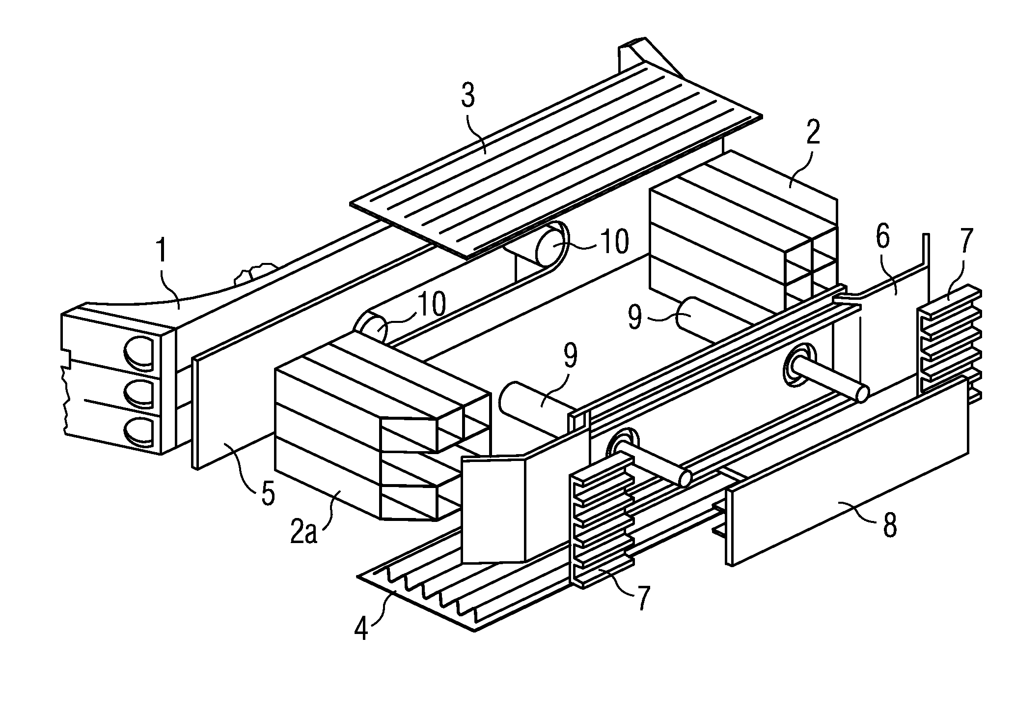
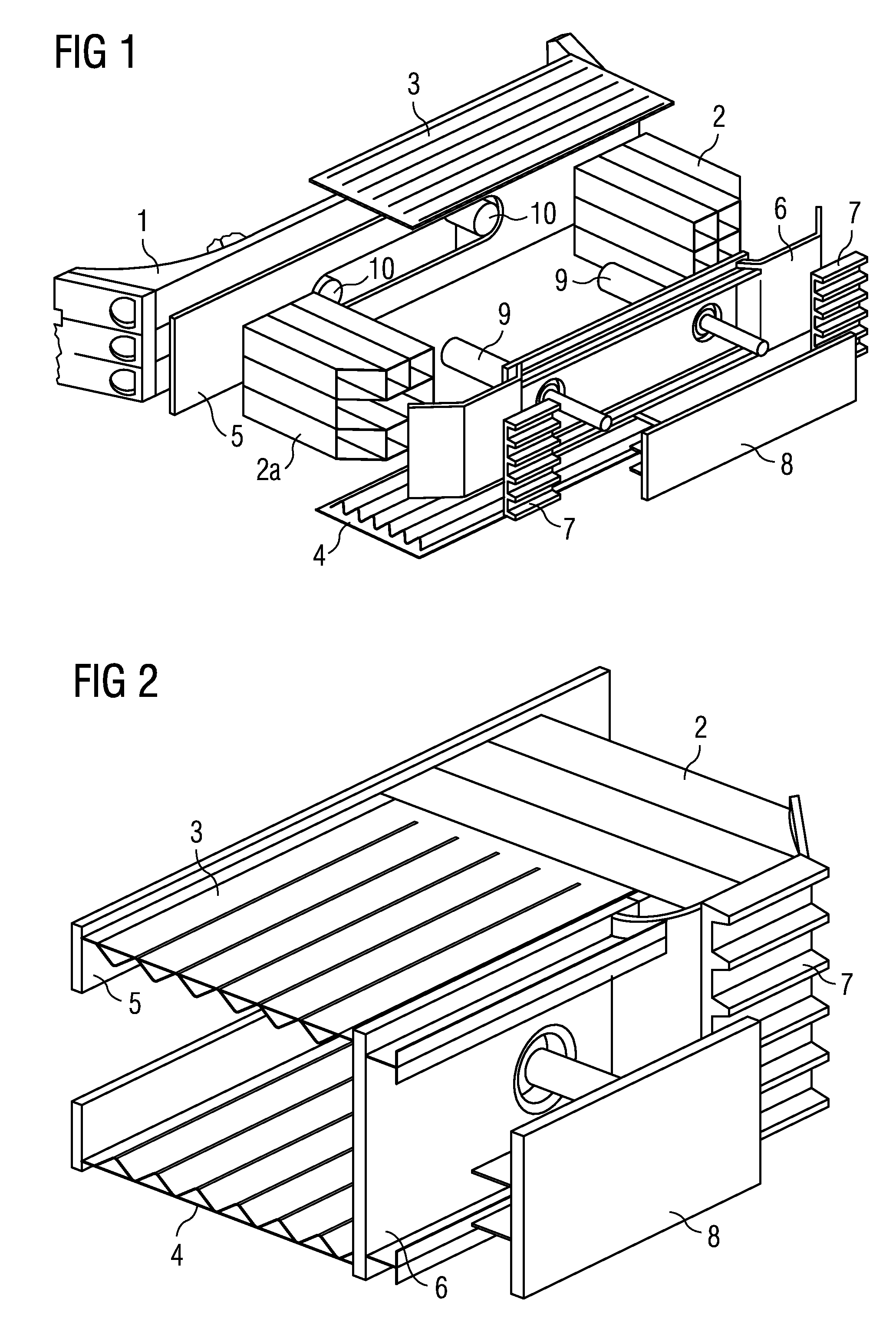
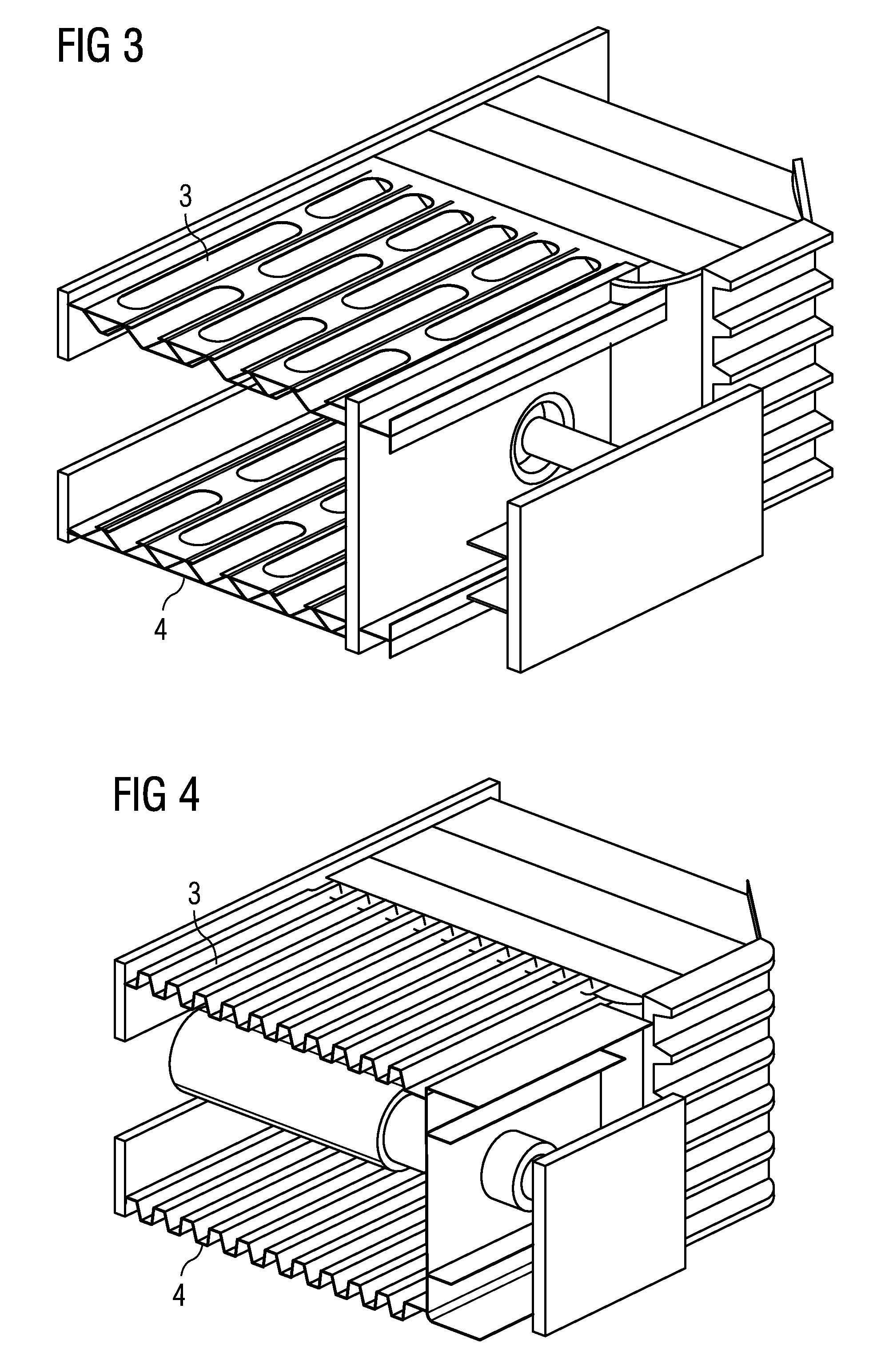
[0034]FIG. 1 shows an exemplary crash module in an exploded schematic view. In the exemplary embodiment illustrated in FIG. 1, a crash module comprises two crash elements 2, 2a which are arranged between a rear connecting plate 5 and a front connecting plate 6. A transverse profiled element 3 and a lower transverse profiled element 4 are in each case arranged in the area bordered by the two crash elements 2, 2a and the connecting plates 5, 6 and can be connected to the said components, for example by means of welded joints. In the exemplary embodiment shown, further components are depicted in the form of two buffer elements 9 which are mounted on the front connecting plate 6 and which have a bumper 8. The front connecting plate 6 is additionally provided with two toothed plates as an anti-climber structure 7. The crash module constructed in such a way is connected to the car body 1. At this connection point the car body 1 has a correspondingly stable receiving possibility to which t...


PUM


Abstract

A crash module for a rail vehicle includes at least one crash element, which is arranged in front of the vehicle structure. At least one transverse profiled element is provided, which is connected to the at least one crash element and which has a substantially lower compressive strength in the longitudinal direction of the rail vehicle than in the transverse direction.

Description

CROSS REFERENCE TO RELATED APPLICATIONS[0001]This application is the U.S. National Stage of International Application No. PCT / EP2010 / 069708, filed Dec. 15, 2010 and claims the benefit thereof. The International Application claims the benefits of Austrian application No. A201 / 2010 AT filed Feb. 11, 2010. All of the applications are incorporated by reference herein in their entirety.TECHNICAL FIELD[0002]The invention relates to a crash module for a rail vehicle, in particular for a streetcar.BACKGROUND ART[0003]Crash zones are frequently incorporated in rail-mounted vehicles in order to improve their deformation behavior in collisions. The aim of these improvement measures is to absorb the impact energy in such a way that crush zones that are deformable in a defined manner convert this energy into deformation energy and in the process the loads to which the persons in the vehicle are exposed are minimized, as well as to ensure that the survival spaces in the vehicle are not too severe...

Claims


Application Information

Patent Timeline
Patent Type & Authority Patents(United States)
IPC IPC(8): B61D15/06
CPCB61D15/06B61F1/10
Inventor GRAF, RICHARDMEISSL, THOMASRITTENSCHOBER, ANDREASSEITZBERGER, MARKUS
Owner SIEMENS MOBILITY AUSTRIA GMBH
Learn More