Industrial protective systems

a protective system and metal electrode technology, applied in the field of metal electrodes, can solve the problems of difficult harvesting of metal growth damage to the outer surface of the edge strip, etc., and achieve the effect of strengthening the edge strip

Inactive Publication Date: 2006-10-05
PAUZE DENNIS A +2
View PDF4 Cites 1 Cited by
  • Summary
  • Abstract
  • Description
  • Claims
  • Application Information

AI Technical Summary

Benefits of technology

[0008] Three-sided edge strips formed in accordance with the invention are monolithic. Where previously corner pieces commonly admitted acid to the underlying portions of the blank, this inhibits the growth of deposited metal. Unlike prior edge strip technologies, spot repairs are easy and quick. Reapplication of the mold or respraying permits the formation in-situ of a new section of edge strip where a damaged area has been removed.
[0009] Polyurethane provides a significantly improved edge strip by virtue of its resistance to the electrolyte and its greater endurance to physical abuse. The edge strips last longer. The manufacturing process to apply the polyurethane edge strip provides substantial cost savings compared to current systems. Linear thermal elongation of the polyurethane edge strip offers superior performance when the blanks are flexed to remove metal deposited thereon.
[0011] In addition, because the improved edge strips need to be removed and replaced less often, substantial labor savings result. Because the polyurethane is substantially 100% solid and inert and even after usage is solvent, CFC, HCFC and VOC-free, disposal is a non-issue. There is no need to haul the polyurethane edge strips to a hazardous waste facility. The regulatory paper trail required for disposal is eliminated and labor is saved in the reduction of transportation of the polyurethane. There is 100% elimination of rolloffs and the maintenance associated with rolloffs.
[0018] In yet a further embodiment, voids in preexisting edge strips are filled with the polyurethane formulation, which advantageously strengthens the edge strips.

Problems solved by technology

If the metal were allowed to grow along the entire blank, encircling it, it would be very difficult to harvest the metal growth, which is typically a 7-day growth that has accumulated on the blank.
Damage to the outer surfaces of the edge strips is a problem.
Exterior surface cracks, cuts, gouges, and nicks on the outer surface of the edge strips are caused by everyday operating procedures such as transportation of the cathodes to receiving racks when harvesting the metal, stripping and transporting back to electrolytic cells.
Damaged areas can allow electrolyte to penetrate through or under the edge strips resulting in irreparable damage to the strips.
Essentially a bad situation quickly becomes a hopeless one.
Once this happens, the edge strip must be replaced as repairs to it are not feasible.
Those corners cannot be adequately sealed so eventually acid finds a void or deteriorates the glue exposing the previously covered portions of the blank, which in turn causes nodule growth that damages the edge strip as described.
A two-sided edge strip, on the other hand, has an additional bottom plug problem.
Again, failures are caused by either acid attacking the glue or by mechanical abuse during transportation and stripping of deposited metal.
This exposure leads to the previously described irreparable damage.

Method used


Image

  • Industrial protective systems
  • Industrial protective systems
  • Industrial protective systems

Examples


Embodiment Construction

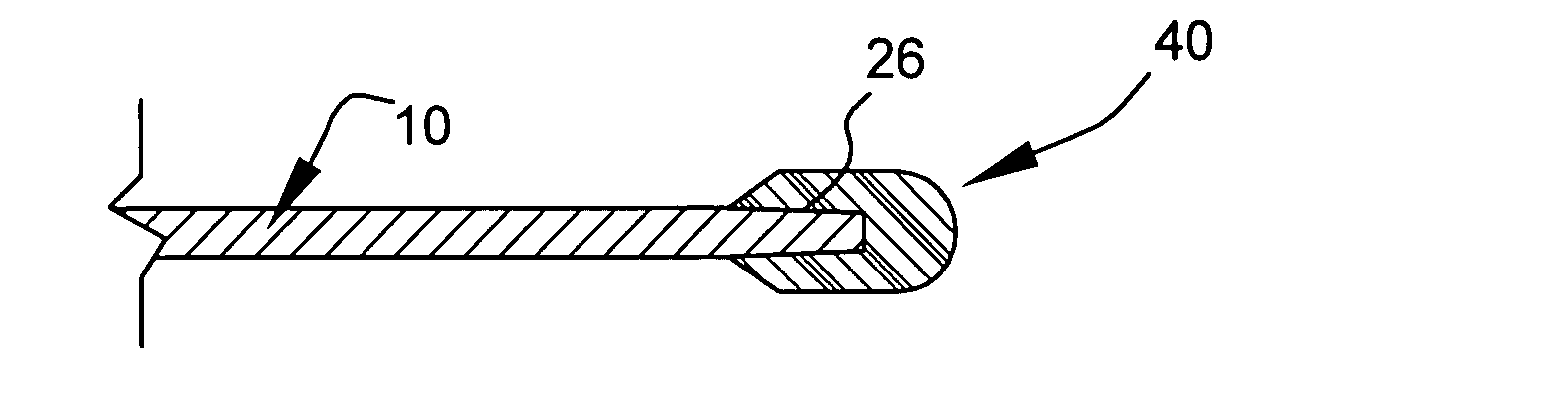
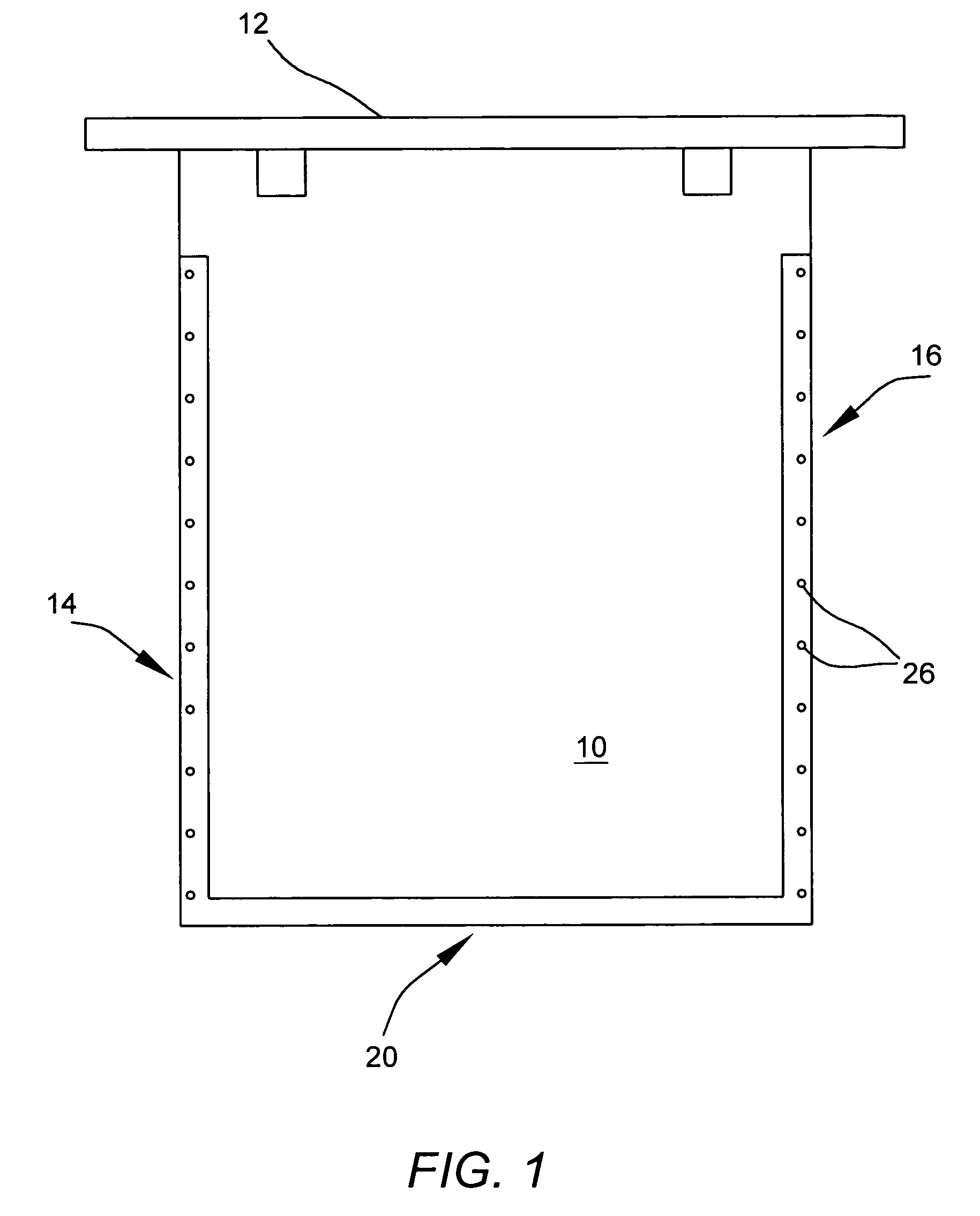
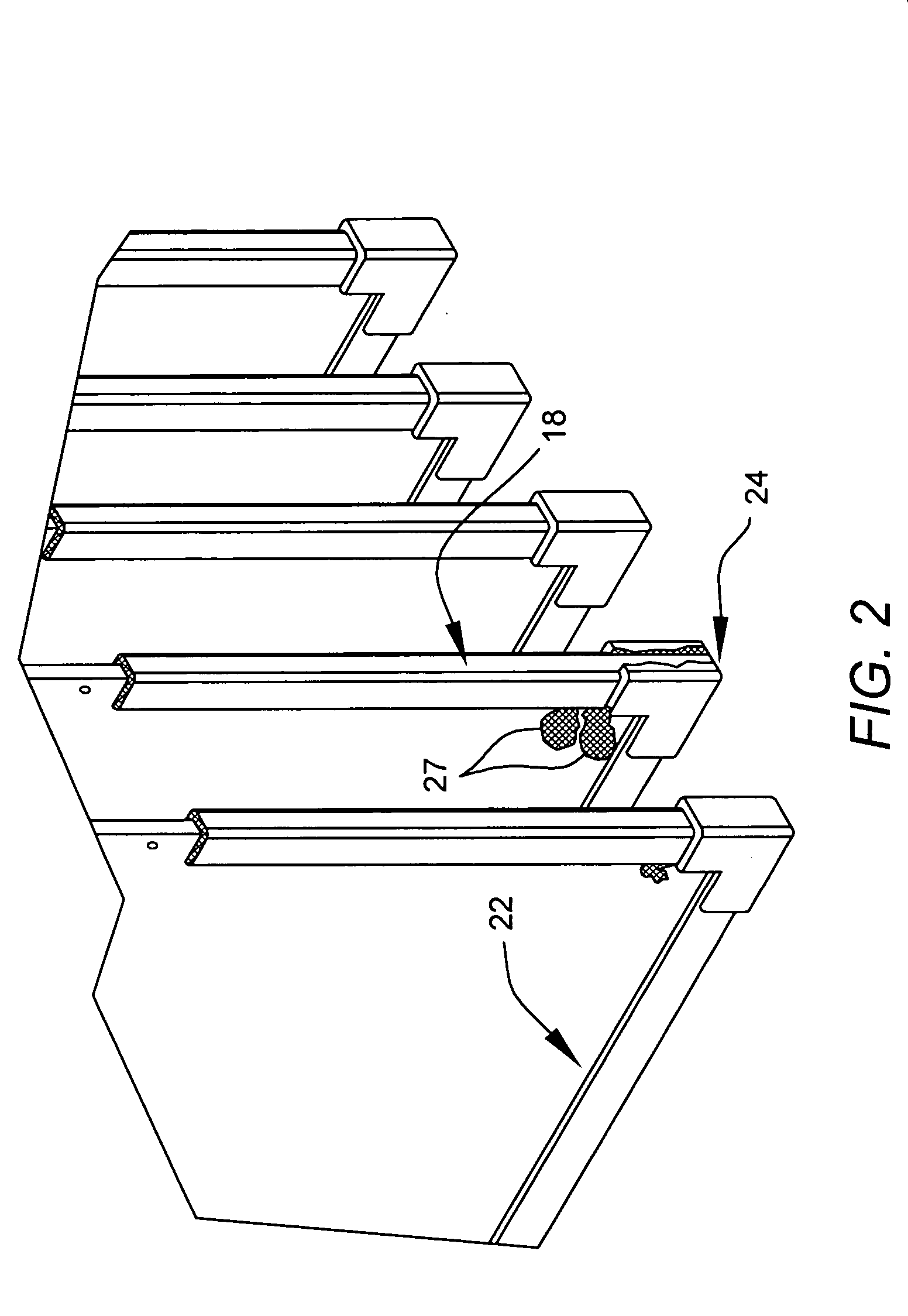
[0027] Turning to FIG. 1 a prior art blank 10 is connected at its upper end with a support member 12 from which it is hung into a cell (not shown) of electrolyte solution in an electrolysis operation. Typically the blank 10 has glued along its two side edges 14 and 16 a pair of edge strips, one of which can be seen in FIG. 2 at 18.

[0028] Where a three-sided edge strip is employed, a further strip 22 similar to the strip 18 in FIG. 2 is glued along the bottom edge 20 of the blank 10. At corners of the blank 10 corner pieces 24 join the edge strips 18 and 22. In the prior art, as illustrated in FIGS. 1 and 2, all of the edge strips and corner pieces are secured to the blank 10 by an appropriate glue. Seen in FIG. 1, small apertures 26 along the edges of the strip help to secure the strips, both in the prior art and the practice of embodiments of the present invention. Two nodules 27 appear in FIG. 2, one at the intersection of the edge strip 18 and the corner piece 24 and one just ab...


PUM

PropertyMeasurementUnit
elongation %aaaaaaaaaa
widthaaaaaaaaaa
elongation factoraaaaaaaaaa

Abstract

A cathode blank used in electrolysis of metal having an improved edge strip. The edge strip is made of a polyurethane formulation having desirable characteristics that prevent electrolyte from leaking into edge strip covered portions of the cathode blank. The edge strip may be molded onto the cathode blank. Alternatively, the polyurethane formulation may also be injected into voids of preexisting edge strips.

Description

FIELD OF THE INVENTION [0001] This invention relates to metal electrodes and more particularly to edge strips formed on cathodes used in metal electrolysis and the method of making those edge strips. BACKGROUND OF THE INVENTION [0002] In electrolysis of metal, electrical current is passed from anodes through a metal-containing electrolyte (e.g., sulfuric acid) to sheet-like blanks that serve as cathodes. The metal is deposited on the blanks by electrolysis. If the metal were allowed to grow along the entire blank, encircling it, it would be very difficult to harvest the metal growth, which is typically a 7-day growth that has accumulated on the blank. The blanks are pulled from the bath and flexed to cause the metal growth to be released. Along two or three edges of the blanks that form the cathodes, edge strips are positioned to prevent the metal growth from extending around the edges of the blanks. [0003] Damage to the outer surfaces of the edge strips is a problem. Exterior surfa...

Claims


Application Information

Patent Timeline
Patent Type & Authority Applications(United States)
IPC IPC(8): B32B3/02B32B3/10
CPCB29C45/14336B29K2075/00B29L2031/265Y10T428/24777Y10T428/24488Y10T428/24331C25C7/02
Inventor PAUZE, DENNIS A.BITNER, CHARLES D. IIIMACDONALD, STACEY A.
Owner PAUZE DENNIS A
Why Eureka
Try Eureka