Pipe repair coupling tool and method of use

a technology of pipe coupling and pipe, which is applied in the direction of pipe joints, sleeves/socket joints, pipe elements, etc., can solve the problems of increasing the difficulty of sliding the coupler along the pipe, increasing the number of trenches, and slipping of the pipe flange, so as to improve the safety of the method of repair and the effect of speeding up and speeding up

Active Publication Date: 2019-01-31
SPRAGUE SCOTT
View PDF5 Cites 1 Cited by
  • Summary
  • Abstract
  • Description
  • Claims
  • Application Information

AI Technical Summary

Benefits of technology

[0005]The invention described herein may be used by pipe layers that would allow for an easier, quicker, and safer method to repair a broken pipe.

Problems solved by technology

This can be difficult and often results in the pry bar slipping off the flange.
Applying an inward and forward force to only one side of the coupler can cock the coupler on a pipe, increasing the difficulty of sliding the coupler along the pipe.
Some of the difficulties associated with the repair process described above relate to the pry bar slipping off the coupler flange, the need to apply inward and forward force on the coupler with the pry bar, and the need for two workers, each with a pry bar to slide the coupler evenly from the original pipe onto the repair section.
The difficulties can result in more workers spending more time in the trench and the increased risk of injury.

Method used


Image

  • Pipe repair coupling tool and method of use
  • Pipe repair coupling tool and method of use
  • Pipe repair coupling tool and method of use

Examples


Embodiment Construction

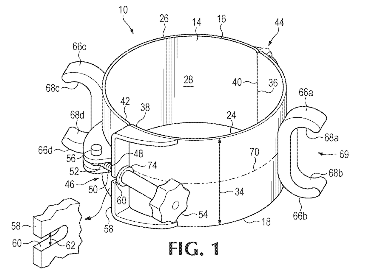
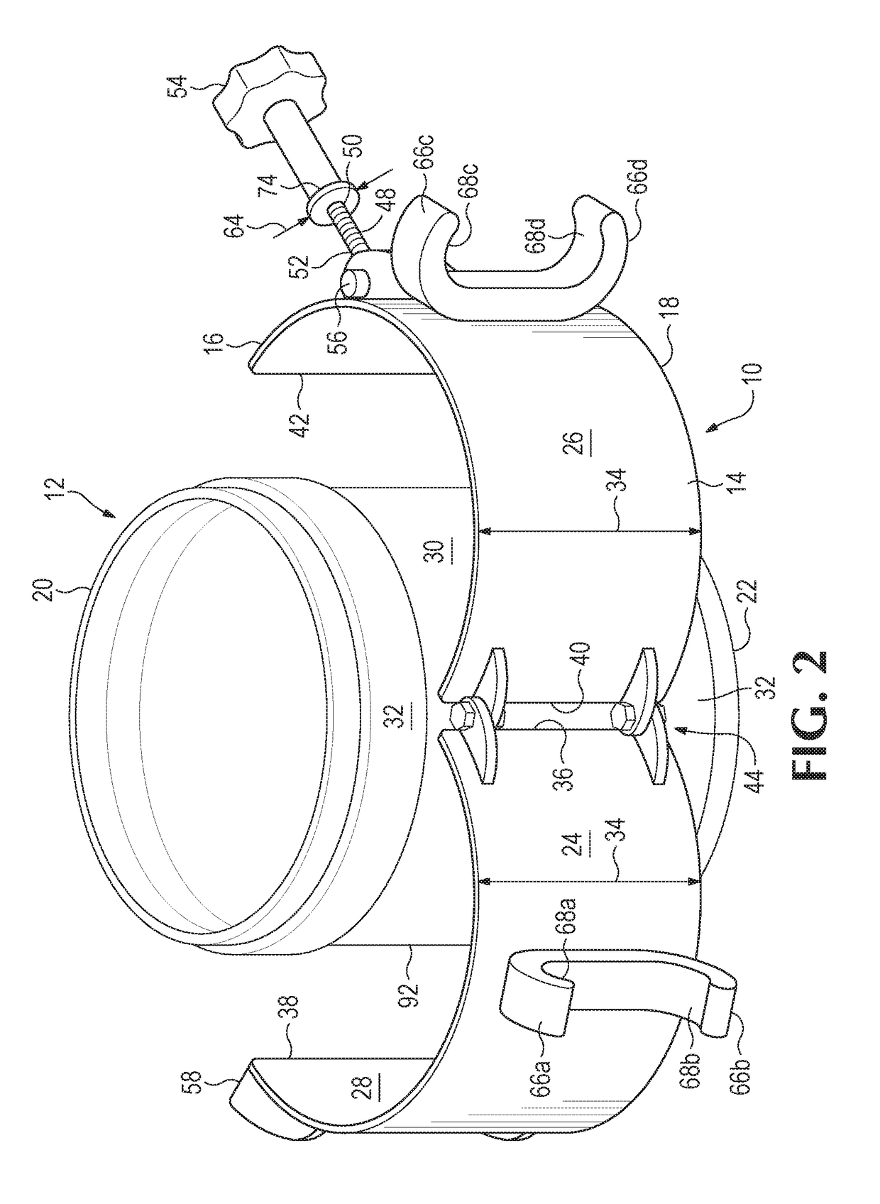
[0016]Referring to the drawings, FIG. 1 shows a pipe repair tool 10 in a first, closed position. FIG. 2 shows the repair tool 10 in a second, open position, partially encircling a coupler 12. In one embodiment of the invention, the repair tool 10 includes a cuff 14, shown in FIG. 1 as having a substantially cylindrical shape with a leading edge 16 and a trailing edge 18 determined by the direction that the repair tool 10 will be moved by a user.

[0017]The coupler 12 may be of the type that is generally available for pipe repair use, and therefore may have a variety of shapes and sizes to accommodate a variety of pipes. In theory the repair tool would be capable of aiding in the repair of a pipe or other conduit of other-than-circular cross-section, but since most pipe is cylindrical, the drawings and description are directed toward a cylindrical conduit. The pipe to be repaired may be of any desired size including, but not limited to, 8 inch, 10 inch, or 12 inch diameter. The coupler...


PUM


Abstract

A pipe repair tool and method of use, for use with a coupler of the type having a first end and a second end, the first end having an outwardly projecting flange, such that the repair tool includes a cuff portion having a leading edge and a trailing edge, the cuff engaging a sleeve portion of the coupler with the leading edge of the cuff facing the flange of the first end of the coupler. The tool may include an outwardly projecting first leading ear having a pry surface near the leading edge of the cuff, the pry surface facing the trailing edge of the cuff such that force applied to the pry surface urges the leading edge of the tool toward the flange of the first end of the coupler.

Description

BACKGROUND OF THE INVENTION[0001]This application relates to a tool to aid in the repair of pipes. For example, to repair buried pipe, workers generally first excavate the surrounding soil and debris from the location of the damaged pipe. Following the excavation, the damaged portion of the pipe is cut away or otherwise removed, leaving two open ends of the original piping.[0002]A pipe repair section, sized to fit the space between the open ends of the original piping, is secured to the original piping with a pair of couplers, one for each joint between the repair section and the original pipe. To accomplish the repair, a single coupler is slid onto each open end of the original piping. The repair section is placed between the exposed ends of the original pipe. Workmen then slide each coupler onto an end of the repair section so that each coupler spans both the replacement pipe section and the original pipe to create two airtight connections between the original pipe and the pipe re...

Claims


Application Information

Patent Timeline
Patent Type & Authority Applications(United States)
IPC IPC(8): F16L55/18F16L21/02F16L55/16
CPCF16L55/18F16L55/1608F16L21/022
Inventor SPRAGUE, SCOTT
Owner SPRAGUE SCOTT
Why Eureka
Try Eureka