Decoding circuit, decoding device, and decoding system

a decoding circuit and decoding device technology, applied in the field of decoding circuits, can solve the problems of insufficient practicality and insufficient normal buffers, and achieve the effect of reducing the buffer size of the decoding circuit and shortening the time required for decoding macroblocks

Active Publication Date: 2014-02-11
PANASONIC CORP
View PDF13 Cites 0 Cited by
  • Summary
  • Abstract
  • Description
  • Claims
  • Application Information

AI Technical Summary

Benefits of technology

[0015]With the above-stated construction, even a decoding circuit, which is required to temporarily store a decoded motion vector in an external memory because of a limit of a buffer capacity of the decoding circuit, transfers a motion vector as follows. The decoding circuit transfers a motion vector that will be needed for a macroblock to be decoded, from the external memory to the buffer in the decoding circuit, before decoding of the macroblock is started. This construction is not necessary unless a macroblock is encoded by the direct mode. However, if the macroblock is encoded by the direct mode, a motion vector of the macroblock can be immediately specified when the macroblock starts to be decoded. As a result, if the macroblock is encoded by the direct mode, a time required for decoding the macroblock can be shortened.
[0016]Also, the buffer transfer instructing unit instructs the transferring unit to transfer the motion vector of the reference macroblock from the external memory to the buffer, during a period from when decoding of a macroblock immediately preceding the current macroblock begins to when the decoding ends.
[0017]With the above-stated construction, while an n-th macroblock is being decoded, a motion vector, to which is referenced when an (n+1)-th macroblock is encoded by the direct mode, is transferred to the buffer in the decoding circuit. Therefore, even if the (n+1)-th macroblock is encoded by the direct mode, a motion vector of the (n+1)-th macroblock can be immediately specified when the (n+1)-th macroblock starts to be decoded. Also, a buffer size in the decoding circuit can be minimized for retaining a motion vector to which is referenced by a succeeding macroblock.

Problems solved by technology

A normal buffer is neither sufficient nor practical for storing so many motion vectors in a decoding circuit.

Method used


Image

  • Decoding circuit, decoding device, and decoding system
  • Decoding circuit, decoding device, and decoding system
  • Decoding circuit, decoding device, and decoding system

Examples


Embodiment Construction

[0041]The following describes an embodiment of the present invention, with reference to the attached drawings.

10>

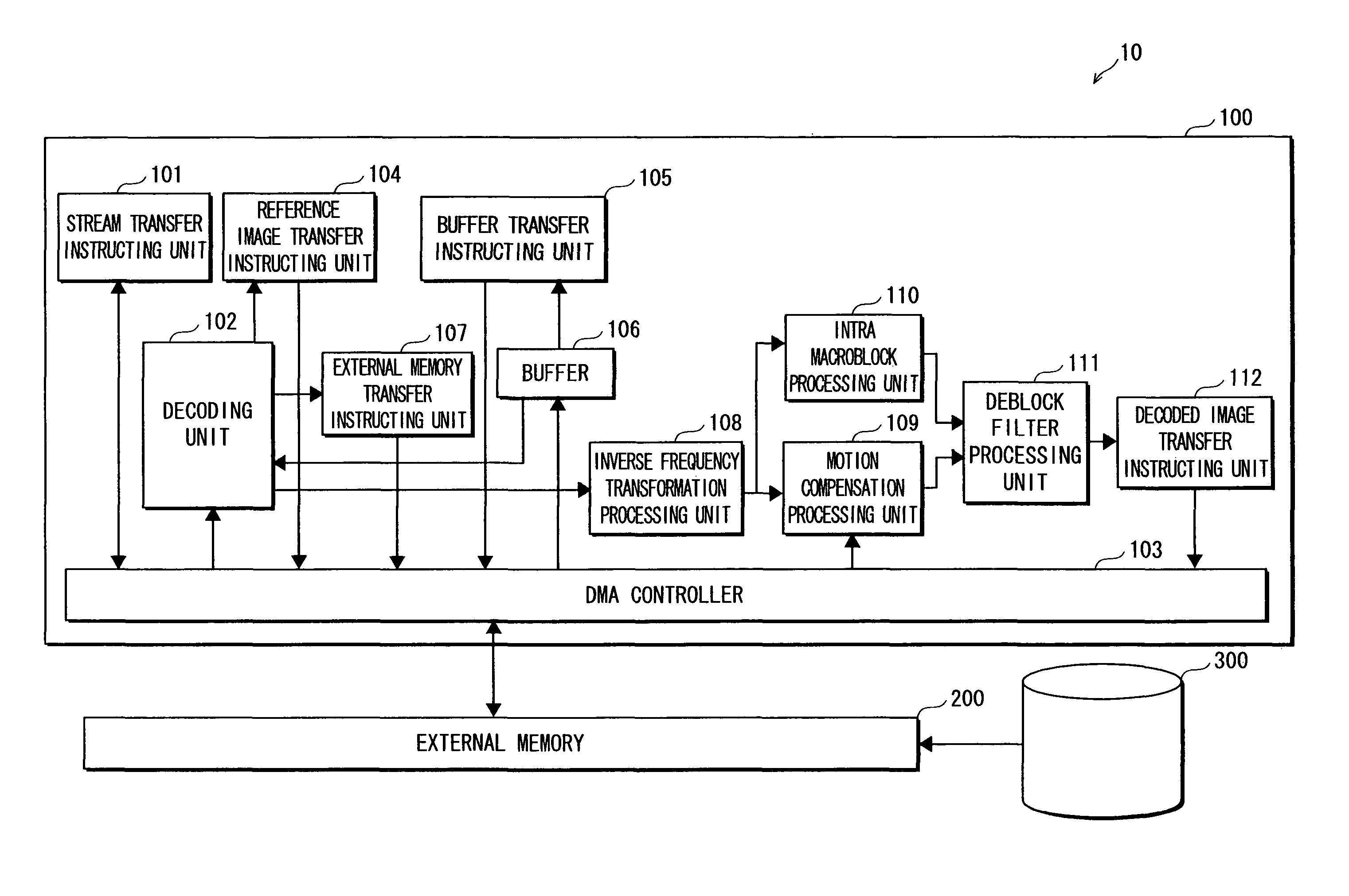
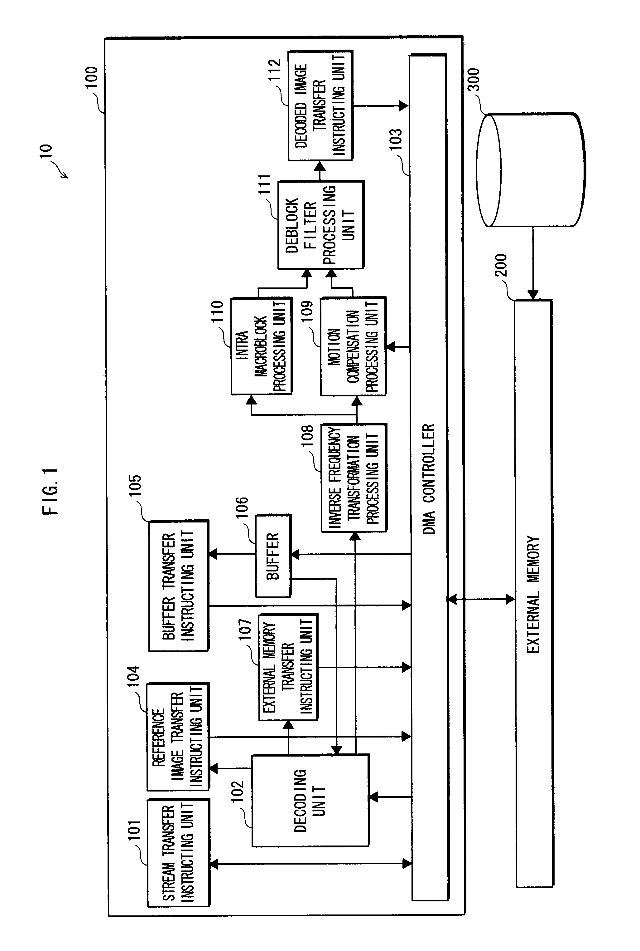
[0042]As shown in FIG. 1, a decoding system 10 includes a decoding circuit 100, an external memory 200 connected to the decoding circuit 100, and a storage medium 300.

[0043]The external memory 200 is a writable memory used as a working area such as a DRAM and the like, and temporarily stores data that is necessary for the decoding circuit 100 to perform a decoding process. The decoding circuit 100 will be described later.

[0044]The storage medium 300 is a mass storage medium such as a HDD (Hard Disk Drive) and the like, and stores moving image data (hereinafter, referred also to as a “stream”) that is encoded according to MPEG. For example, the stream is a TV program recorded by a user.

[0045]The decoding circuit 100 is an integrated circuit for decoding a stream that is encoded according to MPEG. The decoding circuit 100 receives a stream sequentially loaded from the stora...


PUM


Abstract

A decoding circuit, a decoding device, and a decoding system are included for decoding a B picture encoded by a direct mode at a high speed. A decoding process of an n-th macroblock is performed in parallel with transfer of a motion vector of an anchor block for an (n+1)-th macroblock to a buffer 106. With this construction, even if the (n+1)-th macroblock is encoded by the direct mode, a motion vector can be immediately calculated using the motion vector of the anchor block for the (n+1)-th macroblock in the buffer 106, when the (n+1)-th macroblock is decoded during a time T2.

Description

TECHNICAL FIELD[0001]The present invention relates to a decoding circuit, a decoding device, and a decoding system for sequentially decoding a plurality of macroblocks composing an encoded picture in a predetermined order.BACKGROUND ART[0002]A “motion-compensated interframe prediction” is one of important elements of a conventional moving image compression encoding / decoding technology. The motion-compensated interframe prediction is a method for detecting how pictures in continuous frames (screens) composing a moving image move, in order to compress the moving image effectively. In a typical moving image compression method such as MPEG (Moving Picture Experts Group) and the like, when the motion-compensated interframe prediction is performed, the following “motion vector” is used. The motion vector indicates, per unit called a “macroblock” made by dividing a picture, to which direction a current picture moves and an amount of the movement of the current picture compared to a macrobl...

Claims


Application Information

Patent Timeline
Patent Type & Authority Patents(United States)
IPC IPC(8): H04N7/12H04N19/50H04N19/105H04N19/134H04N19/139H04N19/159H04N19/423H04N19/44H04N19/503H04N19/51H04N19/573H04N19/58H04N19/82
CPCH04N19/00721H04N19/00521H04N19/00515H04N19/00684H04N19/00533H04N19/44H04N19/436H04N19/513H04N19/433H04N19/577
Inventor CHIKAMURA, KEISHITANAKA, TAKESHI
Owner PANASONIC CORP
Why Eureka
Try Eureka