Transmission line with rotatable connector

a technology of rotatable connectors and transmission lines, which is applied in the direction of current collectors, coupling device connections, securing/insulating coupling contact members, etc., can solve the problems of bended joint breakage, and achieve the effects of increasing utility, convenient use, and present invention

Inactive Publication Date: 2014-02-18
YFC BONEAGLE ELECTRIC
View PDF45 Cites 32 Cited by
  • Summary
  • Abstract
  • Description
  • Claims
  • Application Information

AI Technical Summary

Benefits of technology

[0007]The present invention provides a transmission line with rotatable connector in order to avoid the breakup of the wires after being repeatedly bended or is bended in one direction for a long period.
[0009]Compared to the known art, the transmission line with rotatable connector of the present invention comprises a rotatable assembly kit. The rotatable cylinder is rotatably and pivotally connected to the rear of the connector. Then the partial transmission line protruding from the insulated body is covered by the wire cover and the partial transmission line horizontally moves along the sliding slot accompany with the rotation of the rotatable cylinder. The transmission line can properly change the direction of the connector to make it convenient for use. The transmission line can also avoid the breakup of the wires from the bending point after being repeatedly bended or is bended in one direction for a long period, thus increases the utility of the present invention.

Problems solved by technology

However, when the transmission line is repeatedly bended or is bended in one direction for a long period, the junction may break up at the bended place.
In addition, the junction of the transmission line usually has non-rotatable structure and when the inserted space or direction has limitation, the junction cannot be inserted properly and causes inconvenience.

Method used


Image

  • Transmission line with rotatable connector
  • Transmission line with rotatable connector
  • Transmission line with rotatable connector

Examples


Embodiment Construction

[0016]Hereinafter, the present invention will be described in detail with reference to the accompanying drawings. It should be understood that drawings do not limit the scope of the present invention.

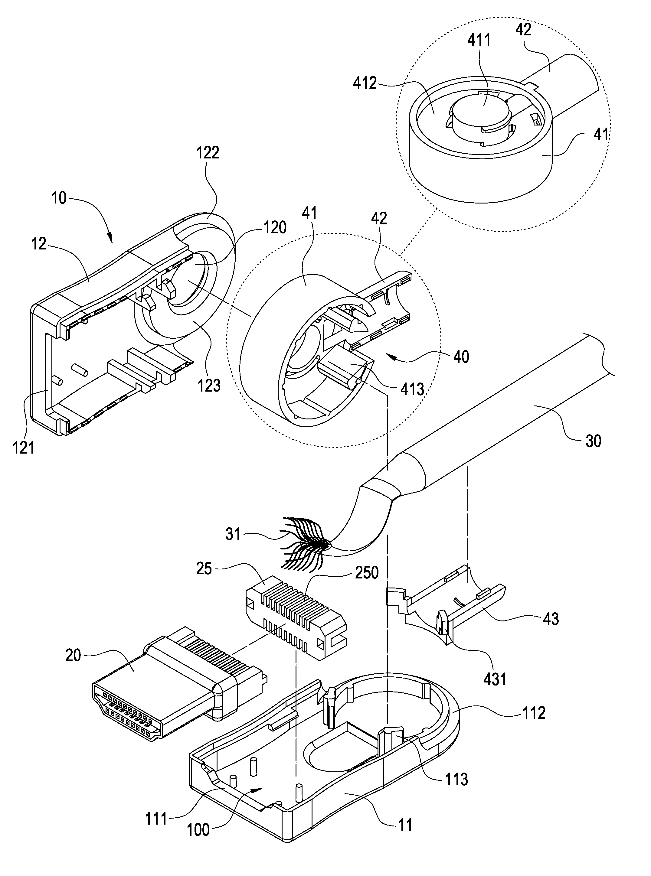
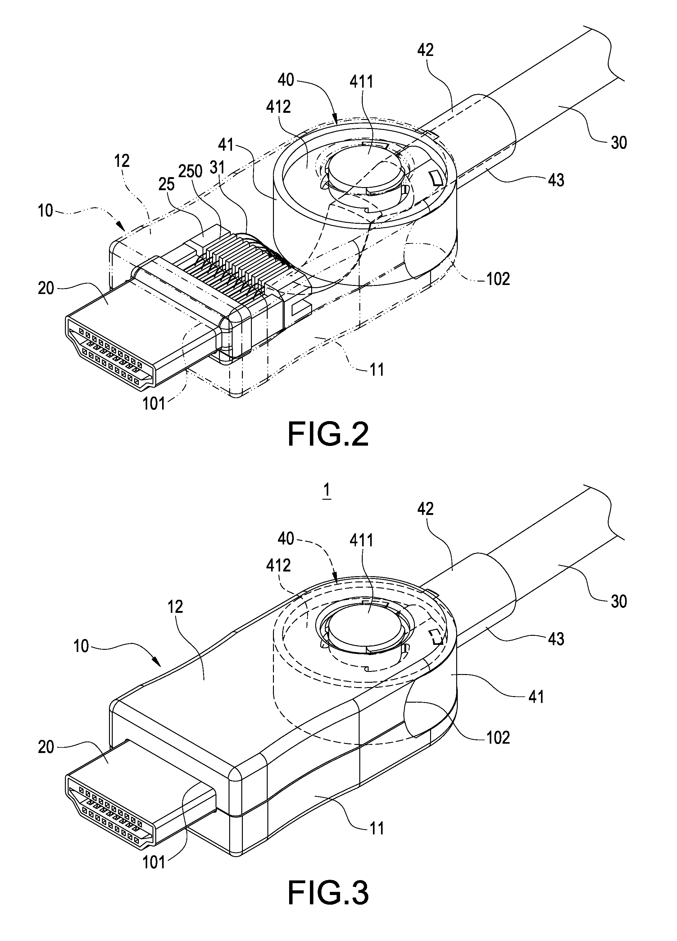
[0017]Please refer to FIG. 1 to FIG. 3, which are respectively the perspective exploded view and two perspective schematic illustrations of one embodiment of a transmission line with rotatable connector. The transmission line with rotatable connector 1 of the present embodiment comprises an insulated body 10, a connector 20, a transmission line 30 and a rotatable assembly kit 40.

[0018]The insulated body 10 may include a storage space 100. The front end of the insulated body 10 may have a square shape and the rear end may have a half-ring shape. In addition, one end (front end) of the insulated body may include an opening slot 101 and the other end (rear end) may include a sliding slot 102. In this embodiment, the insulated body 10 may include a base 11 and a cover 12. The base 11 may in...


PUM


Abstract

A transmission line with rotatable connector includes an insulated body, a connector a transmission line and a rotatable assembly kit. The insulated body includes a storage space. One end of the insulated body includes an opening slot and the other end of the insulating body includes a sliding slot. The connector is inside of the storage space. One end of the connector protrudes from the opening slot. One end of the transmission line is embedded in the storage space and electronically connected with the connector. The other end of the transmission line protrudes from the insulated body. The rotatable assembly kit includes a rotatable cylinder and a wire cover extending from one side of the rotatable cylinder. The rotatable cylinder is rotatably and pivotally connected to the rear of the connector. The partial transmission line protruding from the insulated body is covered by the wire cover and the partial transmission line horizontally moves along the sliding slot accompany with the rotation of the rotatable cylinder. The transmission line can properly change the direction of the connector to make it convenient for use and also can avoid the breakup of the junction of the transmission line at the bending point.

Description

BACKGROUND[0001]1. Technical Field[0002]The present invention relates to a transmission line. More particularly, the present invention relates to a transmission line with rotatable connector.[0003]2. Related Art[0004]With the development of the technology, all kinds of electronic, communication and multi-media devices, such as computer, cell phone, digital camera, DVD, HD television, have been continuously updated. The electrical signal and message between these products may be transferred by a transmission line. When a transmission line is connected to the port of an electronic device, the signal can be transmitted from an electronic device to another electronic device to get the devices connected.[0005]As known to the public, the transmission line may usually be embedded in the connector at the front end of the body and the electronic terminals inside of the connector may be derived from the rear end of the body to weld with wires. Though plastic injection method is generally used...

Claims


Application Information

Patent Timeline
Patent Type & Authority Patents(United States)
IPC IPC(8): H01R39/00
CPCH01R35/02
Inventor KU, YING-MINGCHEN, CHUN-CHIEH
Owner YFC BONEAGLE ELECTRIC
Why Eureka
Try Eureka