Power transmission apparatus

a technology of transmission apparatus and seal, which is applied in the direction of machine/engine, gearing details, drip or splash lubrication, etc., can solve the problem of insufficient lubricant reaching, and achieve the effect of smooth lubrication of seal

Inactive Publication Date: 2014-02-25
GKN DRIVELINE TORQUE TECHNOLOGY KK
View PDF17 Cites 29 Cited by
  • Summary
  • Abstract
  • Description
  • Claims
  • Application Information

AI Technical Summary

Benefits of technology

[0007]An object of the present invention is to provide a power transmission apparatus capable of properly supplying lubricant to a seal arranged between an opening of a case of the apparatus and a shaft that is positioned higher than the other shafts in the case and faces the outside of the case through the opening of the case.

Problems solved by technology

This configuration has a problem that the lubricant will not sufficiently reach a seal arranged between the higher shaft and the opening of the case.

Method used


Image

  • Power transmission apparatus
  • Power transmission apparatus
  • Power transmission apparatus

Examples


first embodiment

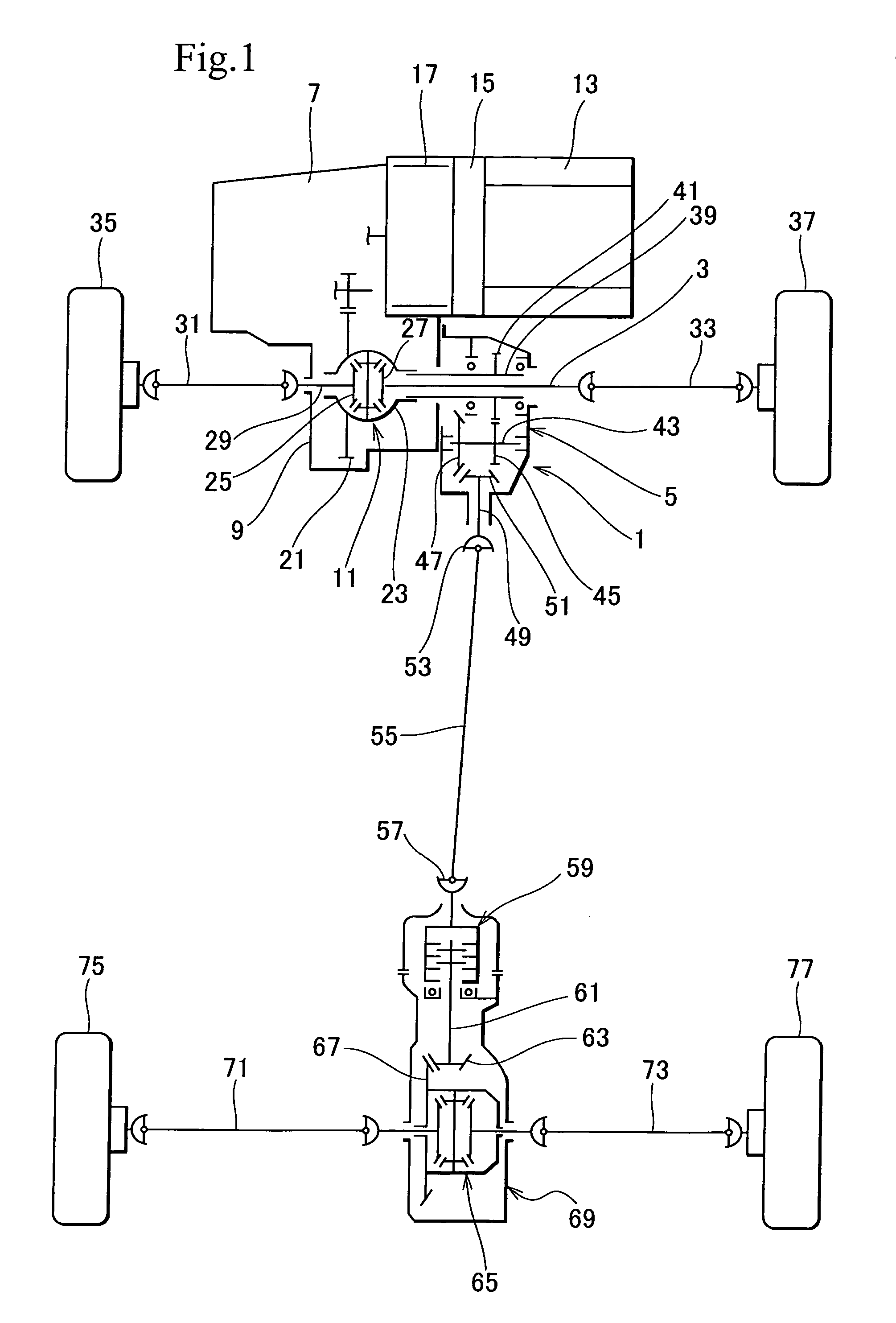
[0026]In the vehicle of FIG. 1, there is arranged a power transmission apparatus 1 according to the present invention. The power transmission apparatus 1 passes therethrough an intermediate axle 3 for front wheels and arranged around the intermediate axle 3. A case 5 of the power transmission apparatus 1 is a transfer case and is attached to a bell housing 9 of a stationary transmission 7.

[0027]The bell housing 9 incorporates a front differential 11. The front differential 11 receives torque from an engine 13 through a main clutch 15, an electric motor 17, and the transmission 7. The torque is transferred through a ring gear 21 to a differential case 23.

[0028]The front differential 11 has left and right side gears 25 and 27 serving as output parts connected to intermediate axles 29 and 3. The intermediate axels 29 and 3 are connected to front-wheel axels 31 and 33, thereby connecting the front differential 11 to the front-wheel axels 31 and 33. The front-wheel axels 31 and 33 are co...

second embodiment

[0085]In FIGS. 6 and 7, the power transmission apparatus 1A of the second embodiment has a lubricant guide 157A. The lubricant guide 157A has a channel 159A that is present only in a second chamber 89. An end of the channel 159A is open above a helical spur gear 45.

[0086]In FIGS. 8, 9, and 10, a case cover 83A according to the second embodiment has a passage hole 175A, a groove 177A, and passage ribs 179 and 181. The ribs 179 and 181 form a part of the lubricant guide 157A and are oriented toward a bearing support 123A. Under the open end of the channel 159A, an inclined rib 183 is formed on the case cover 83A. A lower end of the rib 183 is connected to the passage rib 181.

[0087]The bearing support 123A has a passage groove 184 to guide lubricant from the ribs 179 and 181 toward the back side of a tapered roller bearing 127.

[0088]According to the second embodiment, a ring gear 47 takes up lubricant from a lubricant surface F as indicated with arrows shown in FIGS. 6 and 7. The lubri...

third embodiment

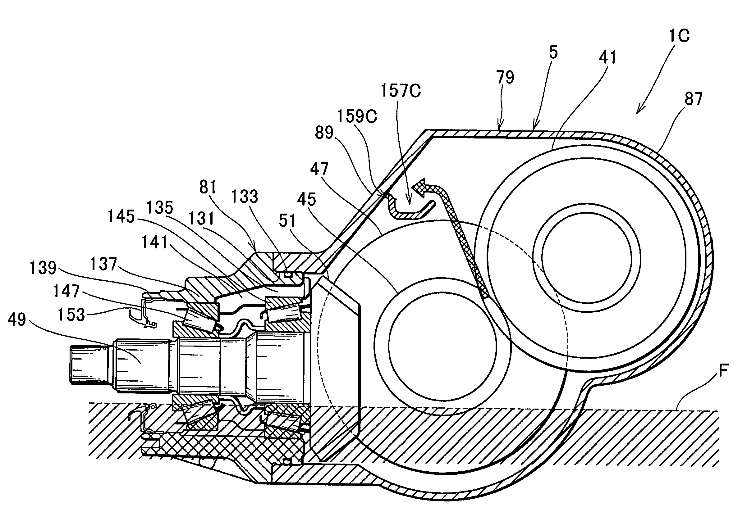
[0093]In FIGS. 11 and 12, the power transmission apparatus 1B has a lubricant guide 157B. The lubricant guide 157B has a channel 159B that is present only in a second chamber 89. The channel 159B is inclined so as to gradually deepen toward the ring gear 47 of the intermediate shaft 43 as the second shaft. An end of the channel 159B is open above a ring gear 47. The channel 159B of the lubricant guide 157B is inclined to receive lubricant splashed by a helical spur gear (parallel meshing gear) 45 and pass the received lubricant toward the ring gear (orthogonal meshing gear) 47.

[0094]According to the third embodiment, the helical spur gear 45 scoops lubricant as indicated with arrows shown in FIGS. 11 and 12. The lubricant is received by the channel 159B and is passed through the open end of the channel 159B above the ring gear 47 toward a tapered roller bearing 125 and an oil seal 103.

[0095]To guide lubricant, the third embodiment may have, like the second embodiment, ribs on an in...


PUM


Abstract

A power transmission apparatus is capable of easily passing lubricant toward a seal arranged between a higher shat and an opening of a case of the apparatus. The apparatus includes the higher shaft, i.e., a hollow connecting shaft that faces the outside of the transfer case through the opening of the transfer case. The oil seal is arranged between the hollow shaft and the opening of the transfer case. The hollow shaft meshes, through helical spur gears, with an intermediate transferring shaft that is positioned lower than the hollow shaft. A lubricant guide is arranged to receive lubricant splashed up by the ring gear and helical spur gear of the intermediate shaft and guide the received lubricant toward the oil seal and a ball bearing.

Description

BACKGROUND OF THE INVENTION[0001]1. Field of the Invention[0002]The present invention relates to a power transmission apparatus of, for example, a vehicle.[0003]2. Description of Related Art[0004]An example of a power transmission apparatus is disclosed in Japanese Unexamined Patent Application Publication No. S62-59130.[0005]The power transmission apparatus of this related art includes a case and three shafts rotatably supported in the case. When gears attached to the shafts rotate, the gears takes up lubricant in the case and the lubricant lubricates seals arranged between openings of the case and the shafts or bearings supporting the shafts.[0006]Among the three shafts, an output shaft for rear wheels, for example, is positioned higher than the other shafts and faces the outside of the case through an opening of the case. This configuration has a problem that the lubricant will not sufficiently reach a seal arranged between the higher shaft and the opening of the case.SUMMARY OF ...

Claims


Application Information

Patent Timeline
Patent Type & Authority Patents(United States)
IPC IPC(8): F16N7/28F16H57/037F16H57/039F01M9/06F16N7/26F16N39/00F16H57/038F01M1/00F16H57/04
CPCF16H57/0423F16H57/0483F16H57/0424
Inventor MATSUMOTO, TAKAYUKINIIMURA, SATOSHIOCHIAI, TOMIAKIIIZUKA, KOJIMASUBUCHI, AKIHIROKAKUTA, MITSUAKIKAWANO, ATSUSHIKASAHARA, MASAHIRO
Owner GKN DRIVELINE TORQUE TECHNOLOGY KK
Why Eureka
Try Eureka