
Method and apparatus for capturing motion of dynamic object

a dynamic object and motion technology, applied in the field of methods and apparatus for capturing the motion of dynamic objects, can solve the problems of large amount of model generating time, unsuitable for generating smooth motion, and large manual labor of skilled designers and artists, and achieve the effect of restoring the motion information of dynamic objects

Inactive Publication Date: 2014-02-25
ELECTRONICS & TELECOMM RES INST
View PDF4 Cites 61 Cited by
  • Summary
  • Abstract
  • Description
  • Claims
  • Application Information

AI Technical Summary

Benefits of technology

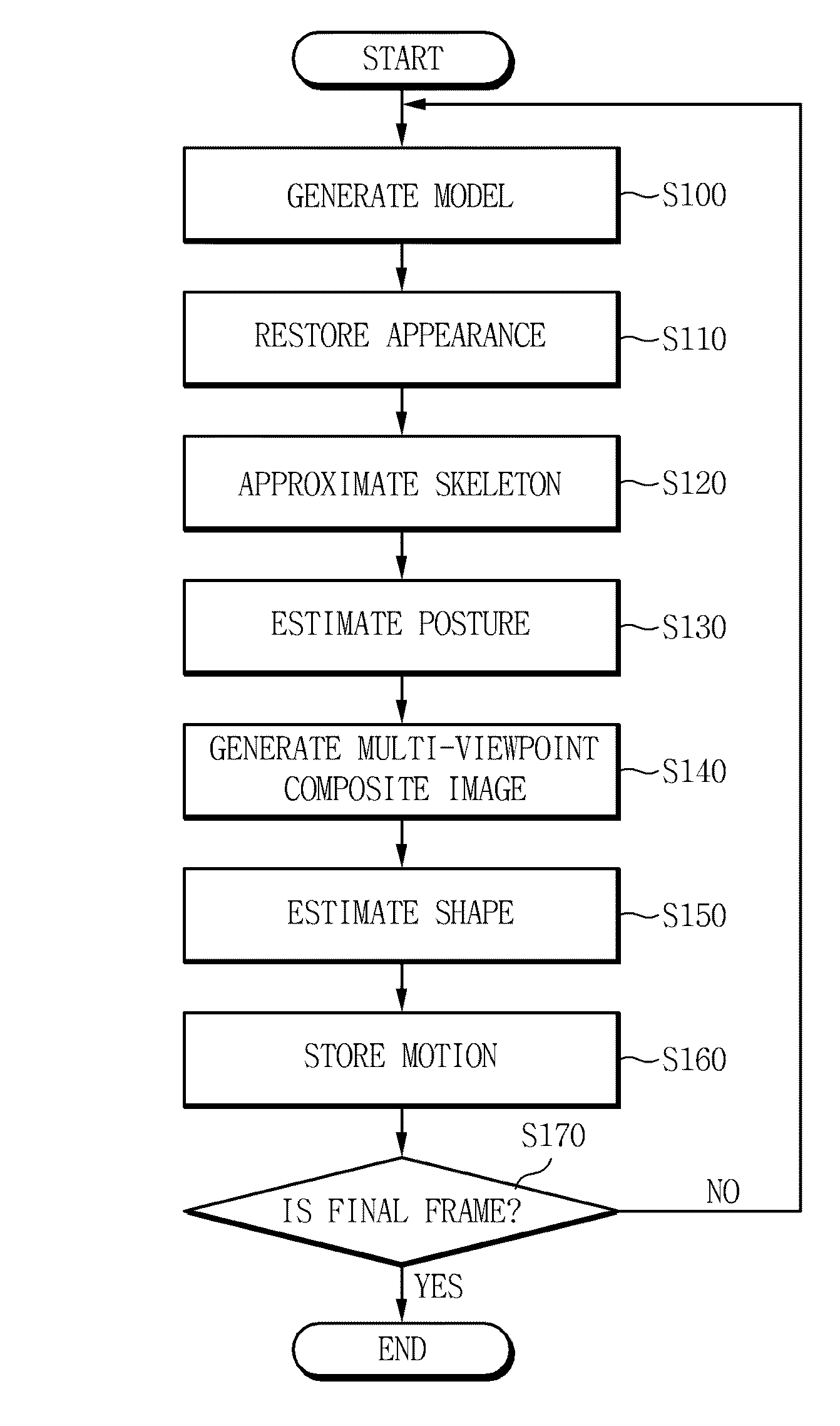
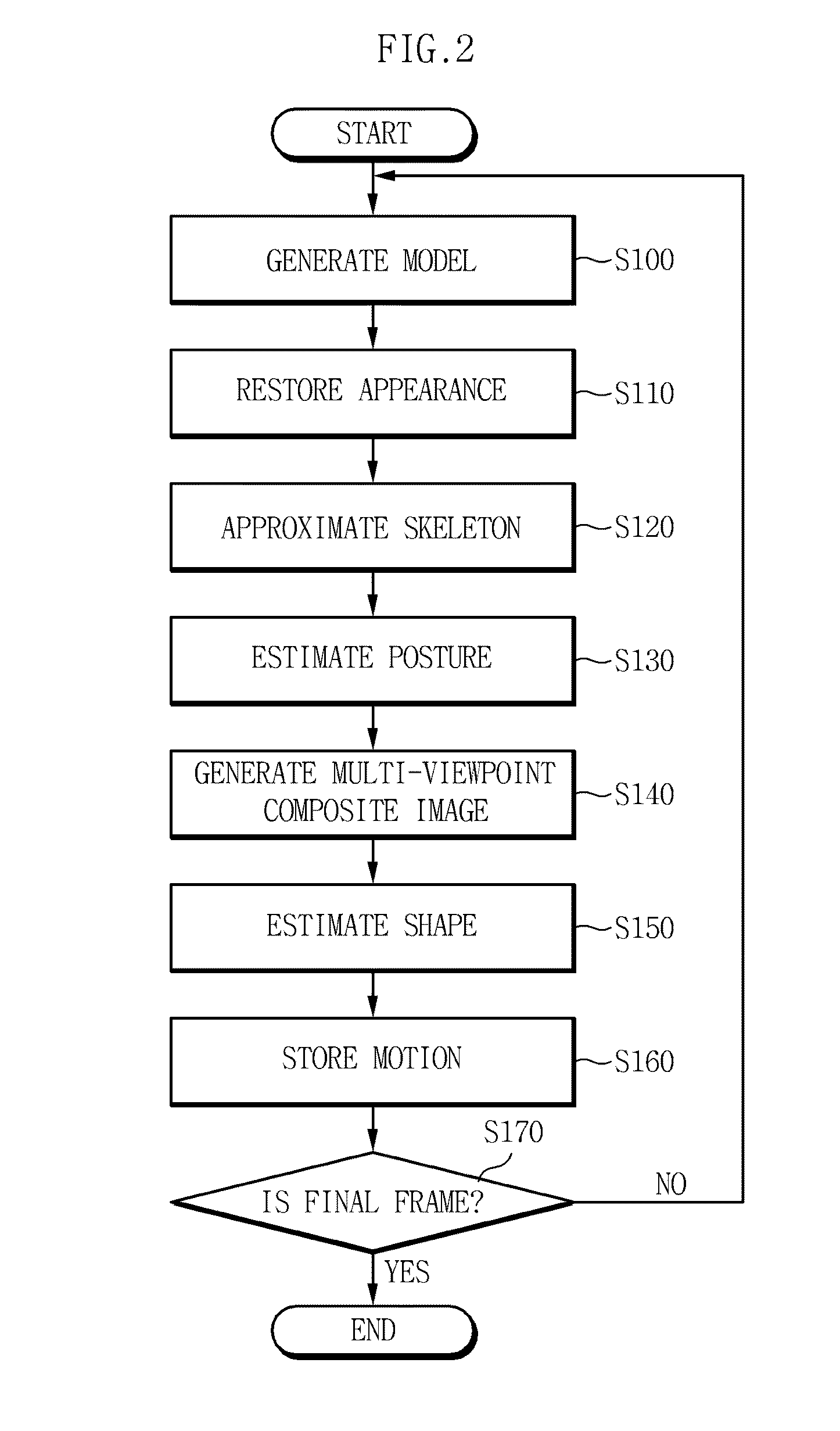
[0023]The estimating the shape may include classifying appearance information of the 3D voxels restored according to part information of the dynamic object, estimating 2D silhouette information lost by self-occlusion by extracting color edge information, close to the boundary of part information projected to the multi-viewpoint image and included in image having similar normal line information, and modifying the shape to minimize a silhouette error of the multi-viewpoint image.
[0024]The estimating the shape may further include estimating a position of a vertex maximally ensuring the curved surface information of a unique tangent line direction of each vertex while minimizing the color error by generating radiation lines from the central point of the 3D cross-section including vertexes of the mesh structure of the 3D model to the vertexes, and performing template matching to the boundary of the 3D visual hull along the radiation lines projected to the multi-viewpoint image having visibility.
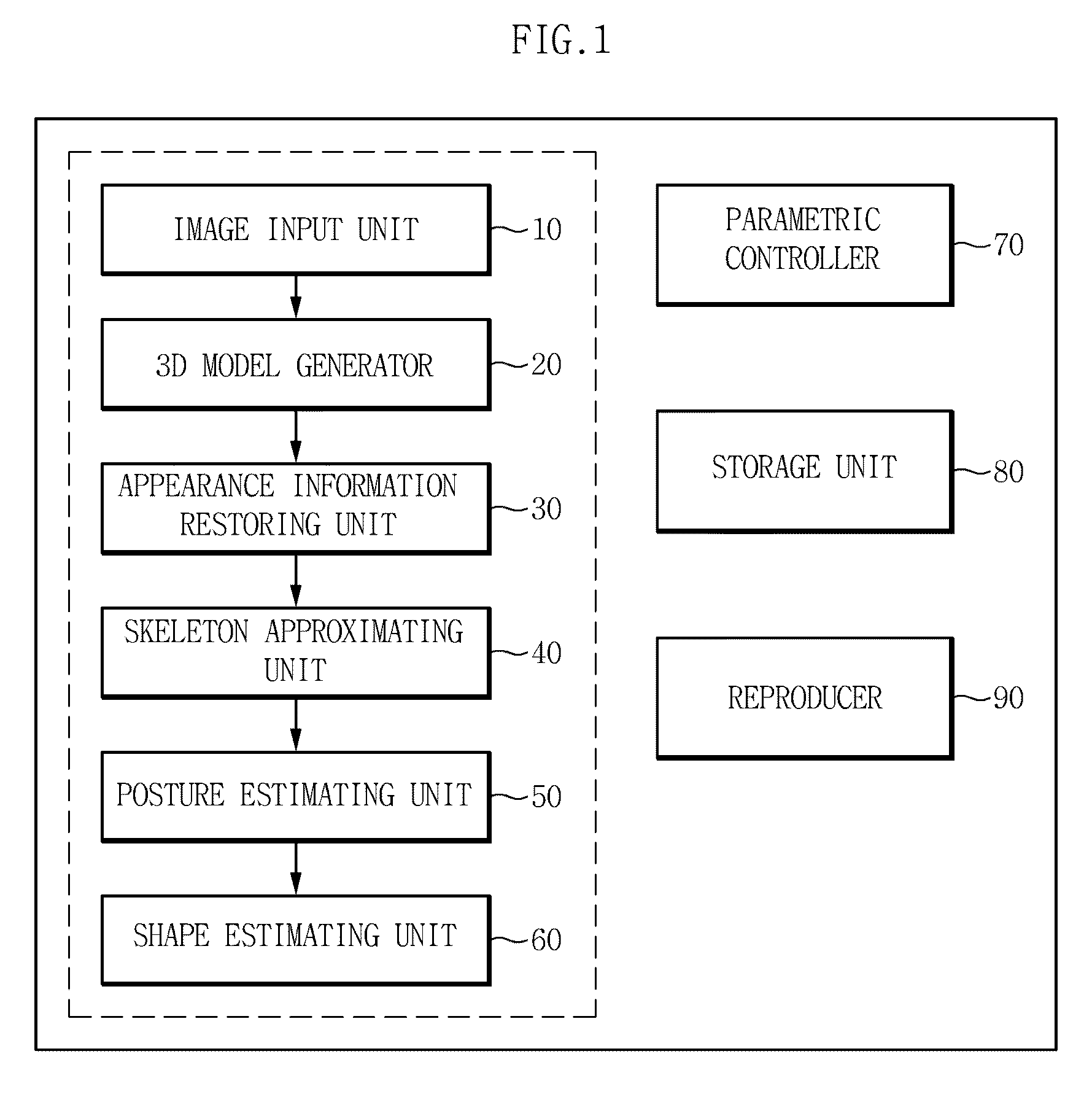
[0032]According to the exemplary embodiments of the present invention, it is possible to minimize a 3D directional error component with respect to a 3D position of each vertex of a 3D model restored through a shape estimation process and a 3D position of each vertex of a 3D model modified by a parametric controller by changing control parameters of muscles and a sweep model.
[0034]Furthermore, it is possible to restore motion information of a dynamic object without attaching a specific marker.

Problems solved by technology

This method is actually used a lot for high-quality special effects in image contents such as films or commercial films; however, there is a drawback in which, in order to combine information obtained by different kinds of sensors, a lot of manual labor of skilled designers and artists and a large amount of model generating time are required.
Scanned static appearance information has a shape different from a mesh structure used for expressing a dynamic motion as in FIG. 3, but it is not appropriate for generating a smooth motion because of excessive capacity and a random structure.
However, it has been reported that, even though multi-viewpoint silhouette information is used, the information has a limit in expressing appearance information of a dynamic object making a dynamic motion, and in order to solve those problems, various correction methods based on user GUI has been suggested.
In a case of a 3D scanning method, there exists a limit in which unique modification features of the appearance, which do not appear when the initial model of the dynamic object, is not properly restored because of limitations in a local-shape modification method based on a mesh used to modify the appearance of the dynamic object.
In a case of a multi-viewpoint image technique, there is a drawback in which, since a modification of an appearance of a dynamic object according to the motion of each frame is restored by using appearance information of an initial model of the dynamic object, the multi-viewpoint image technique is highly dependent on the degree of precision of the appearance of the initial model of the dynamic object.

Method used


Image

  • Method and apparatus for capturing motion of dynamic object
  • Method and apparatus for capturing motion of dynamic object
  • Method and apparatus for capturing motion of dynamic object

Examples


Embodiment Construction

[0043]Hereinafter, restoring a 3D appearance and motion of an object making a dynamic object using a multi-viewpoint camera according to exemplary embodiments of the present invention will be described in detail with reference to the accompanying drawings.

[0044]A dynamic object that is a subject of exemplary embodiments of the present invention maintains a shape on the basis of a skeletal structure, and a restoration subject of exemplary embodiments of the present invention is a living being such as a human body, a dog, and a cat that makes a shape modification and a motion through rotation of inferior joints constituting the skeletal structure, and contraction and relaxation of a muscle structure expressed on the basis of anatomy between joint.

[0045]Exemplary embodiments of the present invention relate to an apparatus and method for capturing an actual motion of a dynamic object geometrically and photographically without using a series of markers by receiving a multi-viewpoint vide...


PUM


Abstract

The present invention relates to a method and apparatus for capturing a motion of a dynamic object, and restore appearance information of an object making a dynamic motion and motion information of main joints from multi-viewpoint video images of motion information of a dynamic object such as a human body, making a motion through a motion of a skeletal structure on the basis of the skeletal structure, acquired by using multiple cameras. According to the exemplary embodiments of the present invention, it is possible to restore motion information of the object making a dynamic motion by using only an image sensor for a visible light range and to reproduce a multi-viewpoint image by effectively storing the restored information. Further, it is possible to restore motion information of the dynamic object without attaching a specific marker.

Description

CROSS REFERENCE TO RELATED APPLICATIONS[0001]This application claims priority to Korean Patent Application No. 10-2009-0126716 filed on Dec. 18, 2009, the entire contents of which are herein incorporated by reference.BACKGROUND OF THE INVENTION[0002]1. Field of the Invention[0003]The present invention relates to a method and apparatus for capturing a motion of a dynamic object, and more particularly, to a method and apparatus for capturing a motion of dynamic object which restore appearance information of an object making a dynamic motion, and motion information of a main joint by only an image sensor for a visible light range.[0004]2. Description of the Related Art[0005]General techniques for capturing appearance and motion information of an object making a dynamic motion are being performed on human bodies and can be generally classified into two kinds.[0006]First, there is a method for capturing a dynamic motion of an object by scanning static appearance information of the object...

Claims


Application Information

Patent Timeline
Patent Type & Authority Patents(United States)
IPC IPC(8): G06T15/00
CPCG06T13/40G06T17/00
Inventor KIM, HO-WONLIM, SEONG-JAEJOO, HAN-BYULKANG, HYUNKOO, BON-KICHU, CHANG-WOO
Owner ELECTRONICS & TELECOMM RES INST
Learn More