Drain and inlet member for drain

a drain and inlet member technology, applied in the field of drains, can solve problems such as leakage risk, and achieve the effect of less leakage risk

Active Publication Date: 2014-03-04
PURUS
View PDF17 Cites 4 Cited by
  • Summary
  • Abstract
  • Description
  • Claims
  • Application Information

AI Technical Summary

Benefits of technology

[0007]The object of the present invention is to propose a drain with a shorter line of contact between the sealing layer and the drain while at the same time the sealing layer is fastened by means of a clamping ring. The result is less risk of leakage and the possibility of connecting an aesthetically more pleasing inlet member, e.g. an inlet member resembling a channel, to a conventional drain.

Problems solved by technology

The channel occupies a large volume and the sealing layer connection runs along the whole frame, entailing risk of leakage.

Method used


Image

  • Drain and inlet member for drain
  • Drain and inlet member for drain
  • Drain and inlet member for drain

Examples


Embodiment Construction

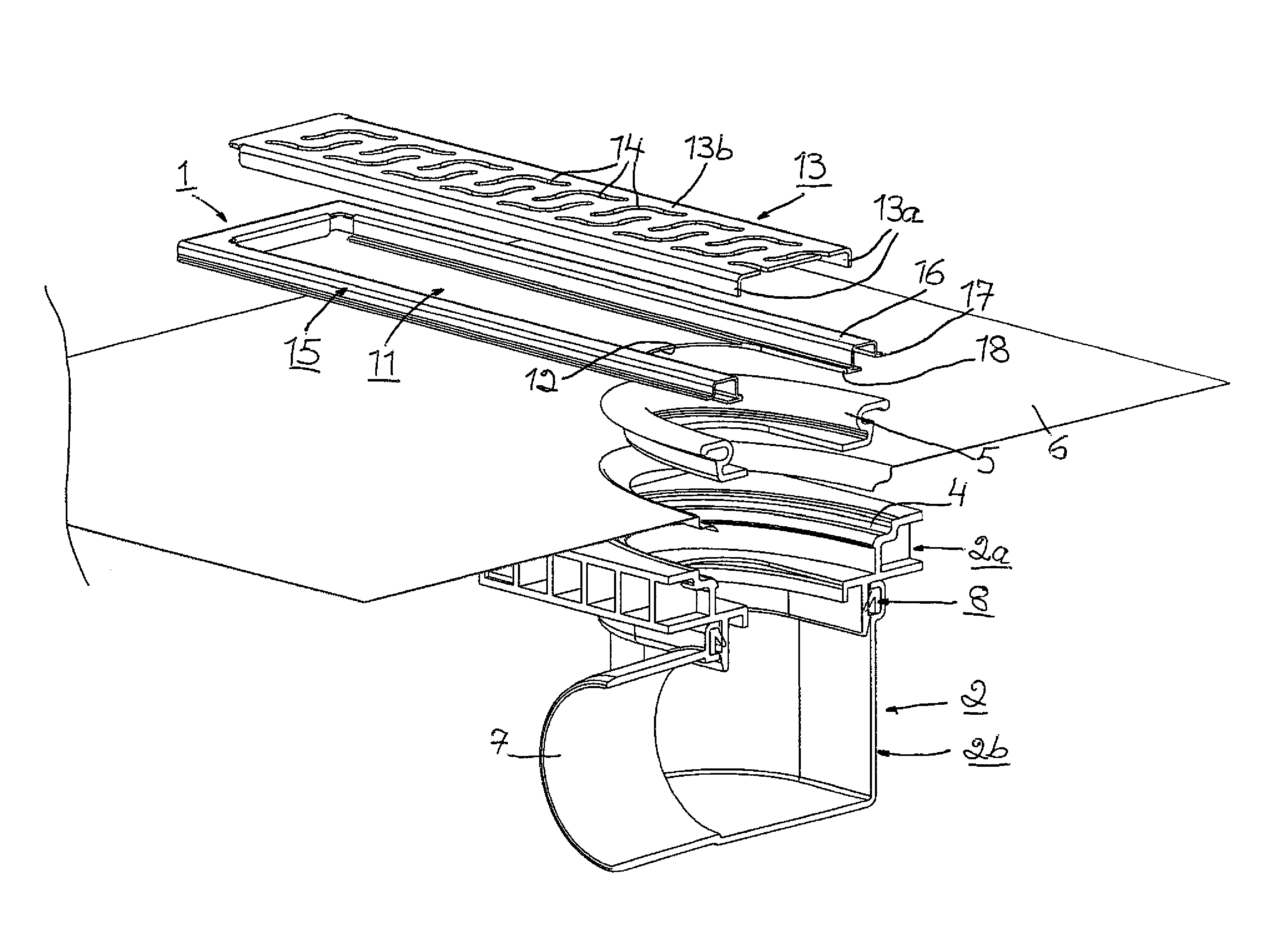
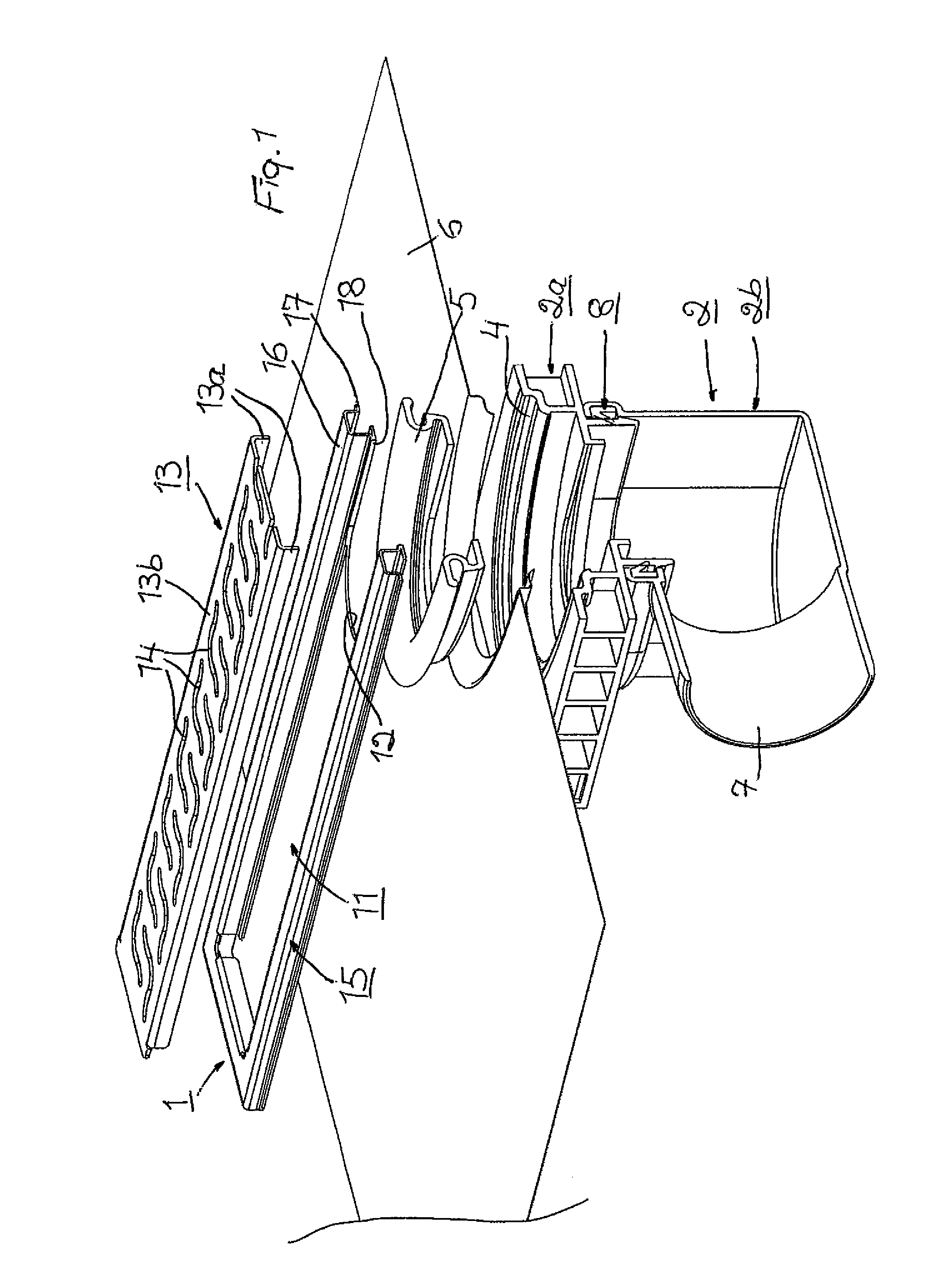
[0020]FIGS. 1-6 thus depict in transverse and longitudinal sections and in perspective two embodiments of a drain according to the present invention with one kind of inlet member, whereas FIGS. 7 and 8 depict a third embodiment of the drain with another kind of inlet member. The inlet members 1 of the drains are also part of the present invention. Each drain comprises not only the inlet member 1 but also an outlet member 2. The inlet member 1 is intended to connect the drain to an undepicted surface covering, e.g. a floor covering. The floor covering may for example consist of clinkers. The outlet member 2 is in flow communication with the inlet member 1 in order to lead liquid via the inlet member from the surface covering to a drain system (not depicted) which is connected to the outlet member.

[0021]The outlet member 2 may, as in the drawings, have a seat 4 for a clamping ring 5 or alternatively have a bonding flange. In order thereby to clamp by means of the clamping ring or to a...


PUM


Abstract

The present invention relates to a drain which comprises an inlet member (1), a grating (13) or cover plate laid loosely or detachably on top of the inlet member, and an outlet member (2). To achieve a short line of contact between the surface covering's sealing layer (6) and the drain while at the same time the sealing layer is fastened by means of a clamping ring (5) or a bonding flange, thereby reducing the risk of leakage and affording the possibility of connecting an aesthetically more pleasing inlet member (1), the inlet member (1) takes the form of an elongate or trilateral plate-like element (11) disposed on top of the sealing layer or the sealing layer (6) and the clamping ring (5) and provided with a recess (12) for flow communication with the outlet member (2). The present invention relates also to an inlet member (1) for a drain as above.

Description

RELATED APPLICATION[0001]This application corresponds to PCT / SE2009 / 0050134, filed Feb. 10, 2009, the subject matter of which is incorporated herein by reference.BACKGROUND TO THE INVENTION[0002]The present invention relates to a drain.[0003]The drain comprises an inlet member for connecting the drain to a surface covering, e.g. a floor covering, and an outlet member which is in flow communication with the inlet member in order to lead liquid via the inlet member from the surface covering to a drain system connected to the outlet member. The drain comprises also a grating or cover plate laid loosely or detachably on top of the inlet member.[0004]The drain's outlet member has a seat for a clamping ring or a bonding flange in order thereby to clamp by means of the clamping ring or to adhesively bond on the bonding flange a sealing layer which is situated under the surface covering and leads down into, and is associated with, the outlet member, and an outlet stub which connects the out...

Claims


Application Information

Patent Timeline
Patent Type & Authority Patents(United States)
IPC IPC(8): A47K3/00
CPCE03F5/0409E03F5/0407E03F5/0408
Inventor LARSSON, HAKAN
Owner PURUS
Why Eureka
Try Eureka