Sealing between a combustion chamber and a turbine nozzle in a turbomachine

Active Publication Date: 2014-03-04
SN DETUDE & DE CONSTR DE MOTEURS DAVIATION S N E C M A
View PDF16 Cites 25 Cited by
  • Summary
  • Abstract
  • Description
  • Claims
  • Application Information

AI Technical Summary

Benefits of technology

[0011]A particular object of the invention is to provide a solut

Problems solved by technology

Those sealing means are therefore relatively complex and the time required for mounting them is relatively lengthy.
Furthermore, those sealing means are not very reliable.
Because of differential thermal expansions between the chamber and the nozzle sectors, and because of the vibration to which the various parts of the sealing means are subjected in operation, it is found that the strips do not always bear against the chamber, in particular duri

Method used


Image

  • Sealing between a combustion chamber and a turbine nozzle in a turbomachine
  • Sealing between a combustion chamber and a turbine nozzle in a turbomachine
  • Sealing between a combustion chamber and a turbine nozzle in a turbomachine

Examples


Example

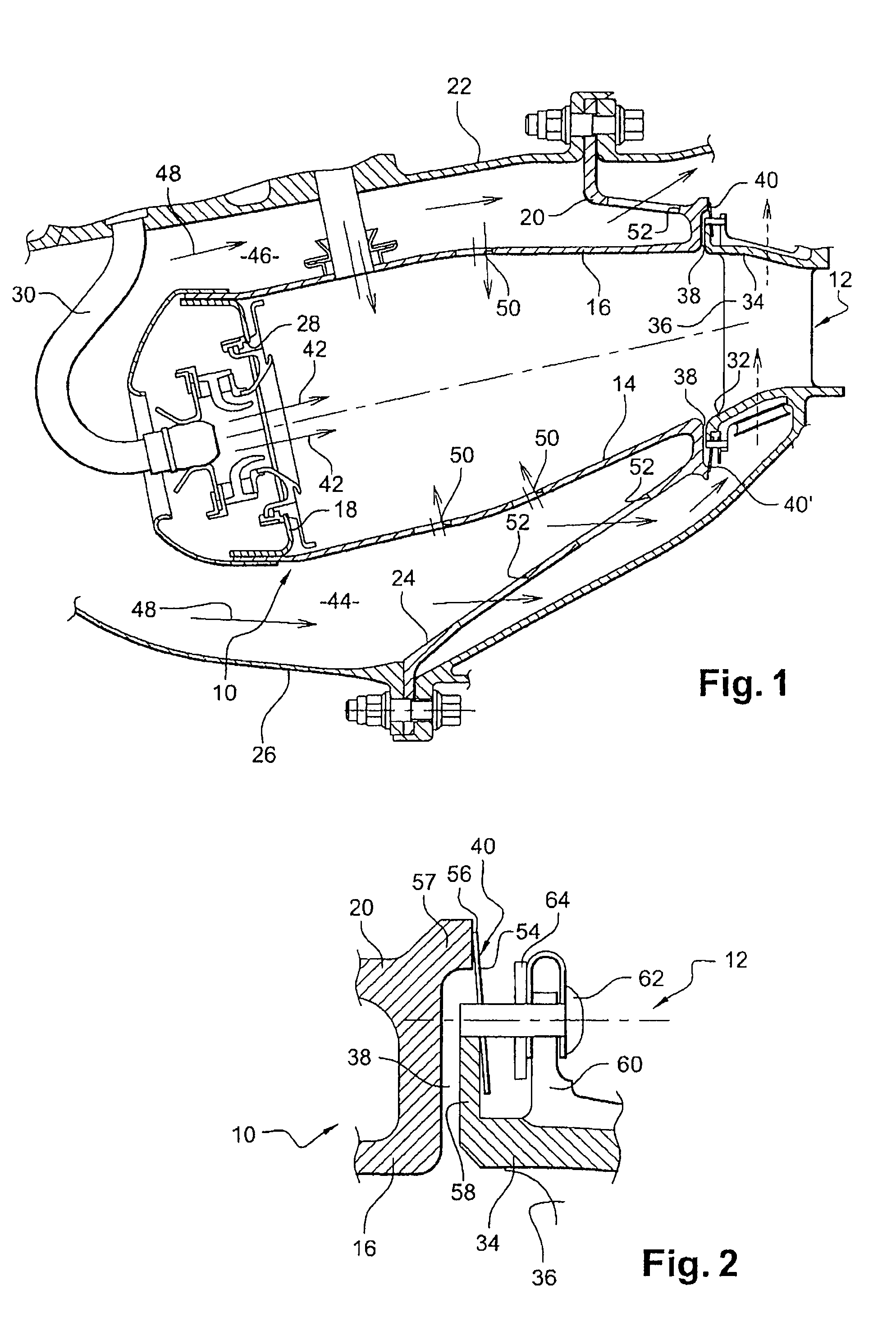
[0033]Reference is made initially to FIG. 1 that shows an annular combustion chamber 10 of a turbomachine, such as an airplane turboprop or turbojet, which combustion chamber is arranged downstream from a compressor and a diffuser (not shown), and upstream from an inlet nozzle 12 of a high pressure turbine 10.

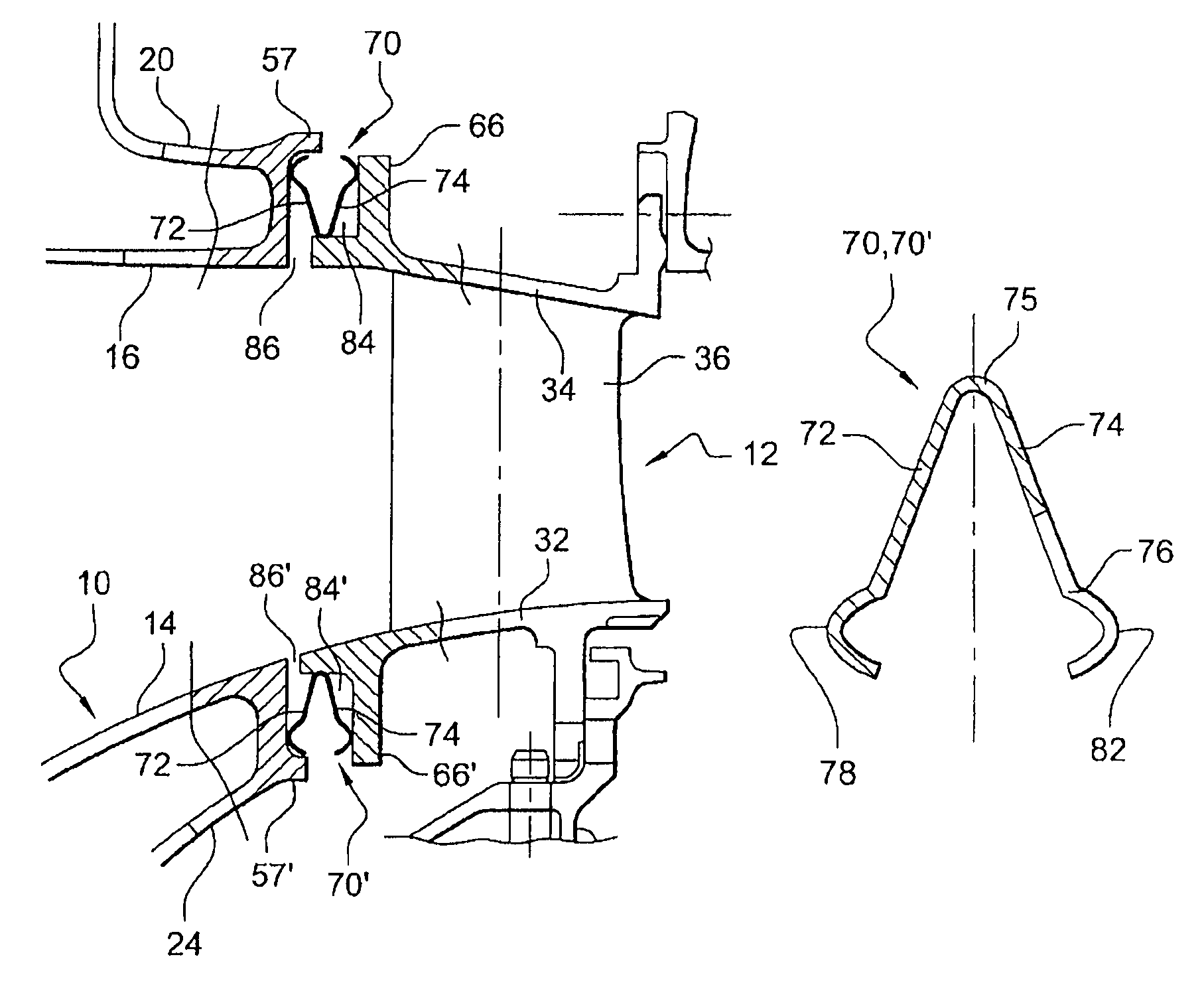
[0034]The combustion chamber 10 has inner and outer walls 14 and 16 forming surfaces of revolution that extend one inside the other and that are connected together at their upstream ends by an annular chamber end wall 18. The outer wall 16 of the chamber is connected at its downstream end to an outer annular flange 20 that is fastened at its outer periphery to an outer casing 22 of the chamber, and its inner wall 14 is connected at its downstream end to an inner annular flange 24 that is fastened at its inner periphery to an inner casing 26 of the chamber.

[0035]The annular chamber end wall 18 has openings 28 for passing air coming from the compressor, together with fuel deliver...


PUM


Abstract

A turbomachine including an annular combustion chamber, a sectorized turbine nozzle arranged at an outlet from the chamber, and a sealing mechanism interposed axially between the chamber and the nozzle, the sealing mechanism including an annular gasket that is axially resilient. The gasket includes a first axial bearing mechanism for bearing against a downstream end of the chamber and a downstream annular lip that is sectorized, each sector of the downstream lip being in alignment with a sector of the nozzle and including a second axial bearing mechanism for bearing against an upstream end of the nozzle sector.

Description

BACKGROUND OF THE INVENTION[0001]1. Field of the Invention[0002]The present invention relates to sealing means between an annular combustion chamber and a turbine nozzle in a turbomachine such as an airplane turboprop or turbojet.[0003]A turbomachine combustion chamber comprises two coaxial walls forming surfaces of revolution constituting respectively an inner wall and an outer wall that define the combustion chamber between them, each of which walls is connected at its downstream end to a respective annular flange for fastening to a casing of the turbomachine.[0004]A sectorized turbine nozzle is arranged at the outlet from the chamber and comprises one or more annular platforms (for example two platforms comprising respectively an inner platform and an outer platform), which platforms are connected together by substantially radial vanes. The inner and outer platforms of the nozzle extend substantially axially in line with the inner and outer walls respectively of the chamber. The ...

Claims


Application Information

Patent Timeline
IPC IPC(8): F02G3/00F02C1/00
CPCF16J15/0887F02C7/28Y02T50/675F01D9/023F01D11/005Y02T50/60
Inventor PIEUSSERGUES, CHRISTOPHESANDELIS, DENIS JEAN MAURICE
Owner SN DETUDE & DE CONSTR DE MOTEURS DAVIATION S N E C M A
Why Eureka
Try Eureka