Antenna, shielding and grounding

a shielding and grounding technology, applied in the field of anti-antenna systems, can solve problems such as negative affecting the wireless performance of the device, and achieve the effects of preventing electromagnetic interference, constant spacing, and minimizing air gaps

Active Publication Date: 2014-03-04
APPLE INC
View PDF51 Cites 39 Cited by
  • Summary
  • Abstract
  • Description
  • Claims
  • Application Information

AI Technical Summary

Benefits of technology

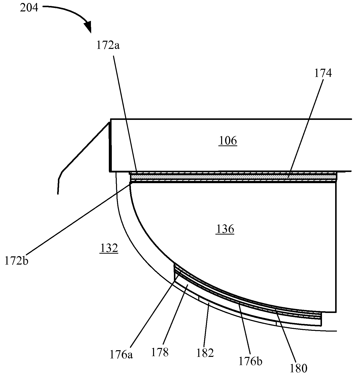
[0014]An antenna system can be disposed within the interior cavity of the housing underneath the cover. The antenna system can include comprising an antenna for transmitting or receiving wireless signals. An adhesive layer for bonding the antenna to a bottom of the cover glass and a compressible foam layer can be provided. The compressible foam layer can be configured to exert an upward force on the antenna to provide a relatively constant spacing between the antenna and the bottom of the cover and to minimize air gaps between the bottom of the cover and the antenna. The relative constant spacing and the minimal air gaps may help to improve the performance of a wireless solution implemented using the antenna.
[0016]In another embodiment, a proximity sensor can be coupled to the antenna carrier, such as by bonding the proximity sensor the compressible foam layer. The proximity sensor can be used to detect objects near the antenna. When an object is detected near the antenna, a power level associated with the antenna can be adjusted. A shield can be disposed between the proximity sensor and the antenna. The shield can be used to prevent electromagnetic interference generated by the proximity sensor from reaching the antenna.
[0017]Another aspect of the invention provides a system. The system can include a metal housing having a surface for receiving a cover glass, a speaker assembly and an antenna system. The speaker assembly can have a) a speaker housing having a metal portion for enclosing at least one speaker driver; b) a connector for grounding the speaker drivers to the metal portion of the speaker housing; c) a conductive material wrapped around the speaker housing for forming a faraday cage around the at least one speaker driver, the conductive material grounded to the metal portion and the metal housing. The antenna system can be mounted to a bottom of the cover glass and to the speaker assembly. Further, the antenna system can be grounded to the metal housing. In one embodiment, the antenna system can be located near one side edge of the metal housing. The thickness of the metal housing on the side edge proximate to the antenna system can be thinned to a performance of the antenna system.
[0018]Another aspect relates to a method of assembling an electronic device having a housing and a cover glass. The method can bonding an adhesive layer to an antenna, coupling a compressible layer of foam to the antenna; and bonding the antenna to the bottom of the cover glass where the compressible foam layer is configured to exert an upward force to the antenna to provide a relatively constant spacing between the antenna and the bottom of the cover glass and to minimize air gaps between the bottom of the cover glass and the antenna.

Problems solved by technology

One challenge to obtaining consistent wireless performance is that materials that are desirable for meeting an aspect of the over-all design different from the wireless performance can negatively affect its wireless performance.
Another challenge to obtaining consistent wireless performance is that, in a compact device with limited packaging space, components that can generate or that can be induced to generate signals that are detrimental to wireless performance can be packaged in close proximity to the antennas.

Method used


Image

  • Antenna, shielding and grounding
  • Antenna, shielding and grounding
  • Antenna, shielding and grounding

Examples


Embodiment Construction

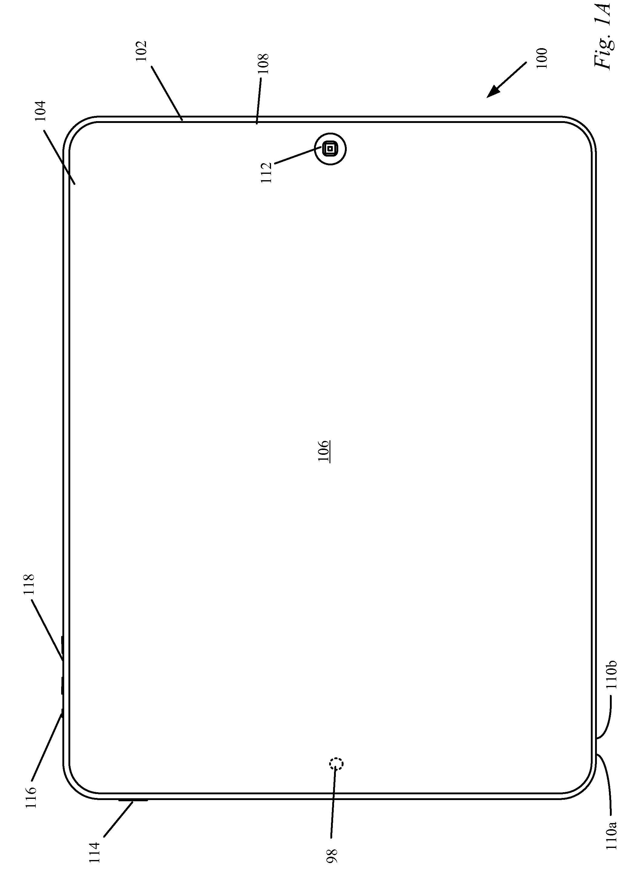
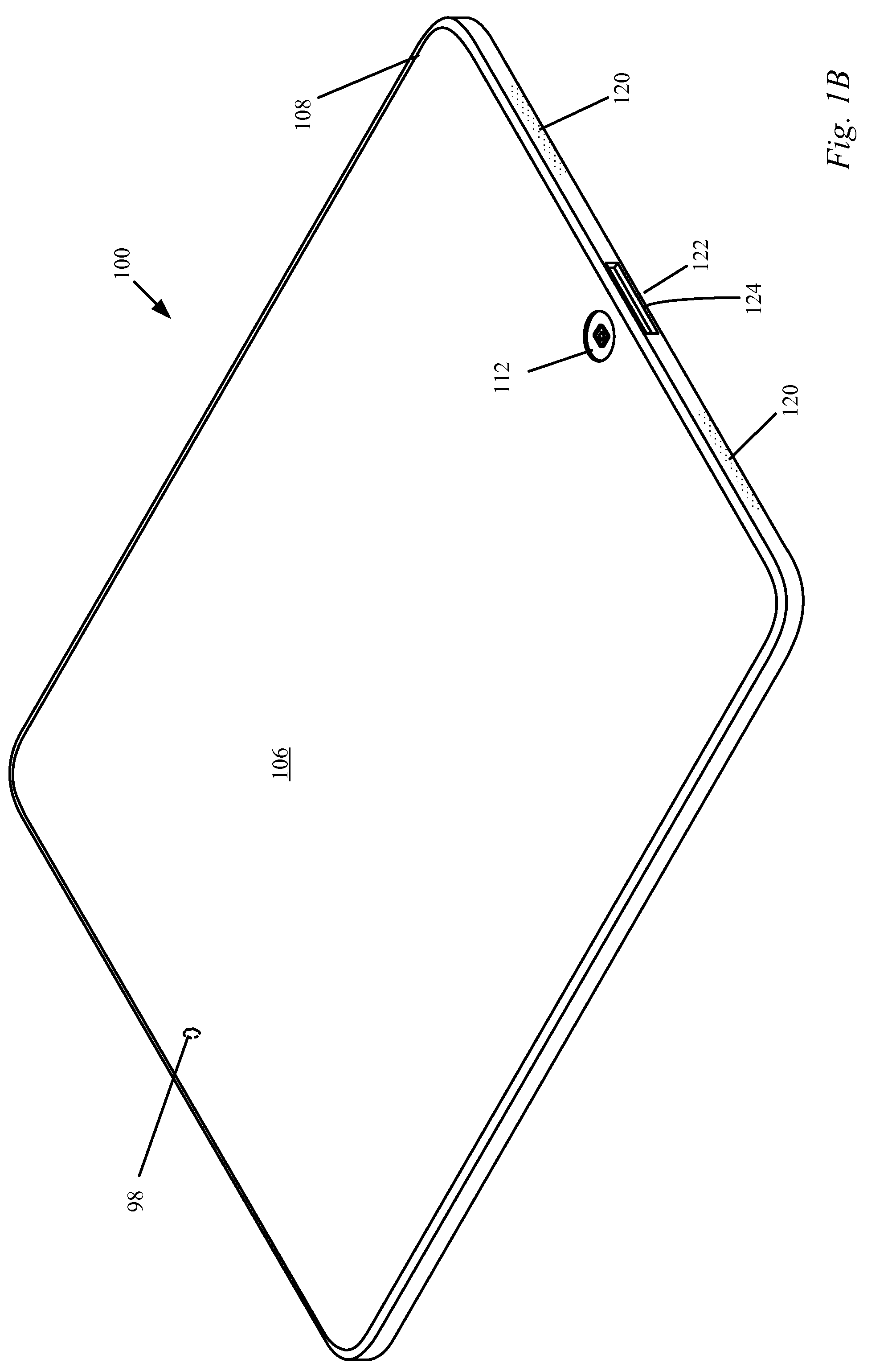
[0007]The described embodiments relate generally to portable computing devices such as laptop computers, tablet computers, and the like. More particularly, antenna systems for portable computing devices and methods of assembling portable computing devices including the antenna systems are described.

[0008]2. Description of the Related Art

[0009]From a visual stand point, users often find compact and sleek designs of consumer electronic devices more aesthetically appealing. As an example, portable electronic device designs that are both thin and light-weight are often popular with consumers. To enable this type of design, the portable electronic device can include a thin profile enclosure and a number of different components disposed inside. For instance, a display, a main logic board including a processor and memory, batteries, audio circuitry, speakers and external interface circuitry can be disposed within the thin-profile enclosure.

[0010]One advantage of a portable electronic devic...


PUM

PropertyMeasurementUnit
thicknessaaaaaaaaaa
thicknessaaaaaaaaaa
distanceaaaaaaaaaa

Abstract

A portable computing device is disclosed. The portable computing device can take many forms such as a laptop computer, a tablet computer, and so on. The portable computing device can include a single piece housing formed from a radio opaque material with a cover formed from a radio transparent material. To implement a wireless interface, an antenna stack-up can be provided that allows an antenna to be mounted to a bottom of the cover. Methods and apparatus are provided for improving wireless performance. For instance, in one embodiment, a metal housing can be thinned to improve antenna performance. As another example, a faraday cage can be formed around speaker drivers to improve antenna performance.

Description

CROSS REFERENCE TO RELATED APPLICATIONS[0001]This patent application is related to and incorporates by reference in their entireties the following patent applications and issued patents:[0002](i) U.S. Pat. No. 8,460,018, entitled “Flat Object Ejector Assembly” by Jules Henry et al.;[0003](ii) U.S. patent application Ser. No. 13 / 018,174, entitled “Handheld Portable Device” by Stephen R. McClure et al.;[0004](iii) U.S. Pat. No. 8,570,736, entitled “Components Assembly” by Stephen R. McClure et al.;[0005](iv) U.S. patent application Ser. No. 13 / 018,242, entitled “Machining Process and Tools” by Stephen R. McClure et al.BACKGROUND[0006]1. Field of the Described Embodiments[0007]The described embodiments relate generally to portable computing devices such as laptop computers, tablet computers, and the like. More particularly, antenna systems for portable computing devices and methods of assembling portable computing devices including the antenna systems are described.[0008]2. Description...

Claims


Application Information

Patent Timeline
Patent Type & Authority Patents(United States)
IPC IPC(8): H01Q1/24
CPCH01Q1/42H01Q1/243H04R1/028Y10T156/1089Y10T29/49016H01Q1/52H01Q1/526H01Q1/2266
Inventor UTTERMANN, ERIK A.FRANKLIN, JEREMY C.MCCLURE, STEPHEN R.CORBIN, SEAN S.LI, QINGXIANGGOMEZ ANGULO, RODNEY A.
Owner APPLE INC
Why Eureka
Try Eureka