Apparatus and Method for Passive Dust Control in a Transfer Chute

a technology of dust control and apparatus, which is applied in the direction of mechanical conveyors, chutes, loading/unloading, etc., can solve the problems of unscheduled shutdown of the conveyor transfer system, difficulty in maintaining a dust-free environment, and emission of dusty environment, so as to reduce noise, minimize the amount of air entrained, and reduce the effect of nois

Inactive Publication Date: 2012-04-19
BROBST STEVEN HAYS
View PDF7 Cites 52 Cited by
  • Summary
  • Abstract
  • Description
  • Claims
  • Application Information

AI Technical Summary

Benefits of technology

[0015]It is therefore an object of the invention to provide a dust control apparatus for a bulk material handling transfer system comprising a chute having a pathway there through for handling varying volumes of bulk material flowing through the chute using gravity flow, and a self-adjusting air restrictor for restricting the air pathway during material volume flow variations to minimize induced air flow. The air restrictor has a mounting system to allow the air restrictor gate to minimize any gap between the air restrictor gate and the material flow, respond to varying flows of bulk material through the chute, and restrict the flow of air through and out the chute to reduce dust emissions. The chute further comprises an entrance zone and an exit zone, wherein a flow of material is received into the chute at the entrance zone from a transfer chute that receives the material via a discharge conveyor, and the material passes through the exit zone of the chute and is expelled onto a receiving conveyor with minimal air flow and dust laden air.
[0016]It is a further object of the invention that the air restrictor comprises a gate member that is hinged off center so that it hangs from an upper wall of the chute when no hulk material is flowing through the chute. The upper wall of the chute may have an access door just below a point where an air restrictor is mounted so that the air restrictor can be easily accessed from outside the apparatus. The dust control apparatus further comprises a counterweight mechanism and a damper system to maintain controlled movement of the air restrictor so that it does not move to quickly or bang against the walls of the chute. The mounting system comprises pivot bearings on each side of the chute for rotatably mounting the support shafts on the gate member. The support shaft is connected to a counterweight mechanism and a damper system that controls the movement of the gate member as it encounters flowing bulk material through the chute.

Problems solved by technology

Induced airflow from the flow of material is a primary cause of airborne dust around conveyor to conveyor transfer chutes.
The resulting airflow mixes with the material dust particles, causing dust-laden air to escape and be released to the surrounding area around the transfer point, thereby creating a dusty environment emanating at the exit of the chute.
If these currently used transfer chutes encounter a large variation in volume of material loading, they have difficulties maintaining a dust-free environment because the chute cannot maintain a material cross-section equal to the fixed chute cross-section.
Alternatively, the chute may become plugged if the material flow is greater than the chute capacity, resulting in an unscheduled shutdown of the conveyor transfer system.
Currently, there exists no other known commercially available technology that can adequately handle varying material flows while minimizing induced airflow and dust in the work area as well as minimizing the risk of plugging.
Some known chutes have difficulties in passively controlling dust-laden air if there are varying material flows.
However, if there are varying loads, then there can be dusting issues.
Basically, some known commercial prior art chutes actively manipulate the material cross sectional area as well as the material flow, which can be problematic and can result in plugging.
Another One known system has recirculation, or stilling, chambers, which has difficulty handling varying material flow and can be physically or commercially unviable due to the size of the needed chambers.
However, this chamber is not always an effective way to minimize the dust because the air that goes into the chamber mixes with the bulk material and must exit from the chamber one way or another.
This chute works well with a constant flow of material, but it does not always work well if the flowing material is too sticky because sticky material causes the chute to get plugged.
The curtains are flexible and are un-dampered allowing them to distort and bouncing; with the result that large gaps between material, curtain, and side walls are available for dust laden air to escape the transfer system.
However, it is difficult and time-consuming to move the chute, the variation of material flow is not easily handled by this system, and the chute can potentially plug if not adjusted swiftly enough.
However, in a typical conveyor system, the material capacities are rarely constant.
However, it was not an adequate solution to the problem of dust control due to automatic control challenges and economics.

Method used


Image

  • Apparatus and Method for Passive Dust Control in a Transfer Chute
  • Apparatus and Method for Passive Dust Control in a Transfer Chute
  • Apparatus and Method for Passive Dust Control in a Transfer Chute

Examples


Embodiment Construction

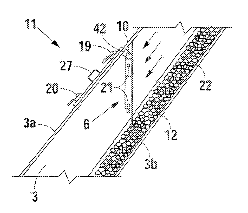
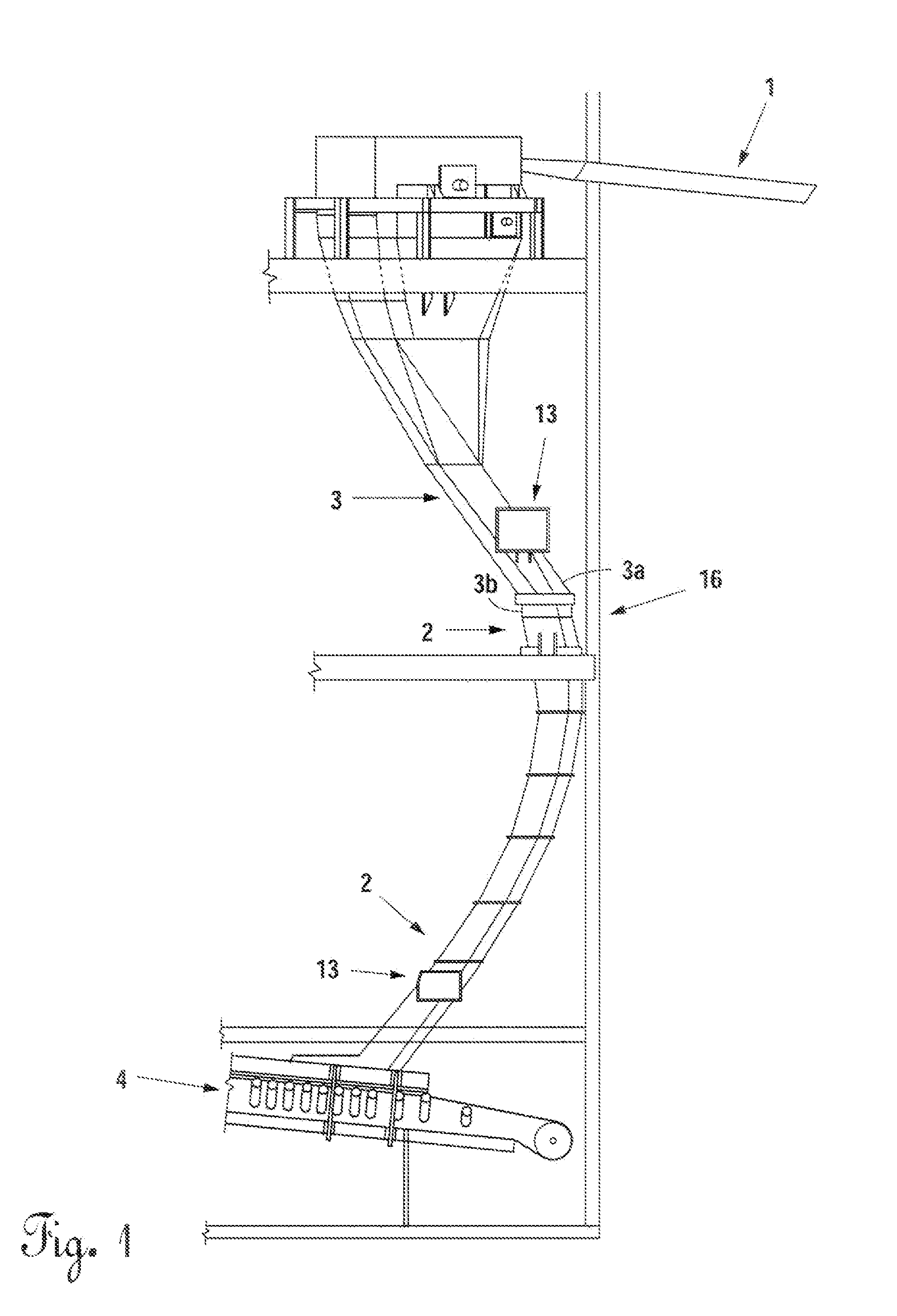
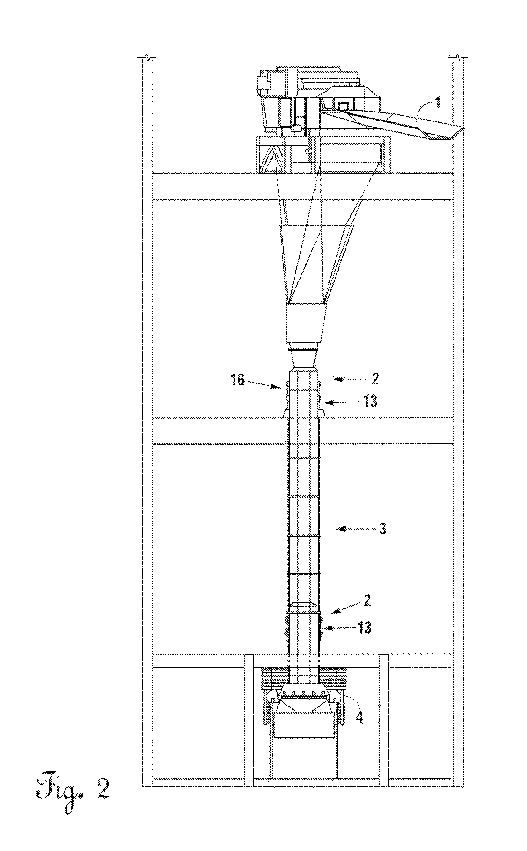
[0035]A preferred embodiment of the instant invention is shown in typical installations such as shown in FIGS. 1 and 2. Dust control apparatuses 13 are shown installed into a bulk material transfer system 16. Multiple dust control apparatuses could be used depending on the type of transfer chute involved. The discharge conveyor 1 at the upper or top portion discharges bulk material 12 (see FIGS. 7-10) into the transfer chute 3, where the material runs down and along the transfer chute lower wall 3b. The material then passes through the one or more air restrictor locations 2 positioned along the chute and finally exiting the transfer chute 3 onto the exit conveyor 4 at the bottom of the chute.

[0036]Referring to FIG. 3, a dissected top view of the dust control apparatus 13 is shown. The transfer chute opening 5 is shown in the shape of a modified hexagon, but it may be in other geometric shapes, depending on the shapes of the transfer chute 3. The air restrictor gate or baffle 6 has a...


PUM


Abstract

A dust control apparatus and method for a bulk material handling transfer system having a chute comprising a pathway there through for handling varying volumes of bulk material flowing through the chute using gravity flow. A self-adjusting air restrictor gate is mounted in the chute for engaging the upper surface of flowing bulk material through the chute for restricting the air pathway during material volume flow variations to reduce dust emissions. The gate member contacts the upper surface of flowing bulk material and moves up and down in response to the flow of bulk material through the chute to restrict the flow of air to reduce dust. A counterweight mechanism and a damper helps maintain controlled contact of the air restrictor gate with the upper surface of bulk material flowing through the chute.

Description

CROSS-REFERENCE TO RELATED APPLICATIONS[0001]Applicant claims priority based on Provisional Application No. 61 / 392,669 entitled Air Restrictors for Bulk Material Handling Transfer Systems; Filed on Oct. 13, 2010STATEMENTS REGARDING FEDERALLY SPONSORED RESEARCH AND DEVELOPMENT[0002]N / AFIELD OF THE INVENTION[0003]The present invention relates generally to dust control systems. More specifically, the invention relations to a dust control system for transferring material from an upper conveyer to a lower conveyer by passing it through a transfer chute. During transfer of the material through the chute, the present invention minimizes induced airflow through the transfer chute and across the material. In this manner, dust emissions emanating from the material is greatly reduced and contained during transfer. Furthermore, the invention allows there to be adjustable capacity of the chute so that material flow through the chute may be increased or decreased as necessary while maintaining du...

Claims


Application Information

Patent Timeline
Patent Type & Authority Applications(United States)
IPC IPC(8): B65G11/20B65G37/00
CPCB65G69/181B65G11/206
Inventor BROBST, STEVEN HAYS
Owner BROBST STEVEN HAYS
Why Eureka
Try Eureka