Transfer device and image forming apparatus incorporating transfer device

a transfer device and image forming technology, applied in the direction of electrographic process apparatus, instruments, optics, etc., can solve the problems of -described conventional techniques cannot obtain a fine image, likely induced transfer error,

Active Publication Date: 2012-01-12
RICOH KK
View PDF9 Cites 45 Cited by
  • Summary
  • Abstract
  • Description
  • Claims
  • Application Information

AI Technical Summary

Benefits of technology

[0013]In another aspect, the engaging and disengaging device includes a cam having at least two different cam portions changing a size of the gap when rotated, a cam driving device that rotates and stops the cam, and a cam controller that controls the cam driving device. The cam controller controls the cam driving device to rotate and stop the cam at a first angular position minimizing the gap when the adjustment pattern passes therethrough.

Problems solved by technology

Although the sharp increase in load can be avoided by broadening the shaft distance as shown in the JP-H10-83124-A, a transfer error is likely induced due to shortage of transfer pressure.
However, the above-described conventional techniques cannot obtain a fine image.

Method used


Image

  • Transfer device and image forming apparatus incorporating transfer device
  • Transfer device and image forming apparatus incorporating transfer device
  • Transfer device and image forming apparatus incorporating transfer device

Examples


first embodiment

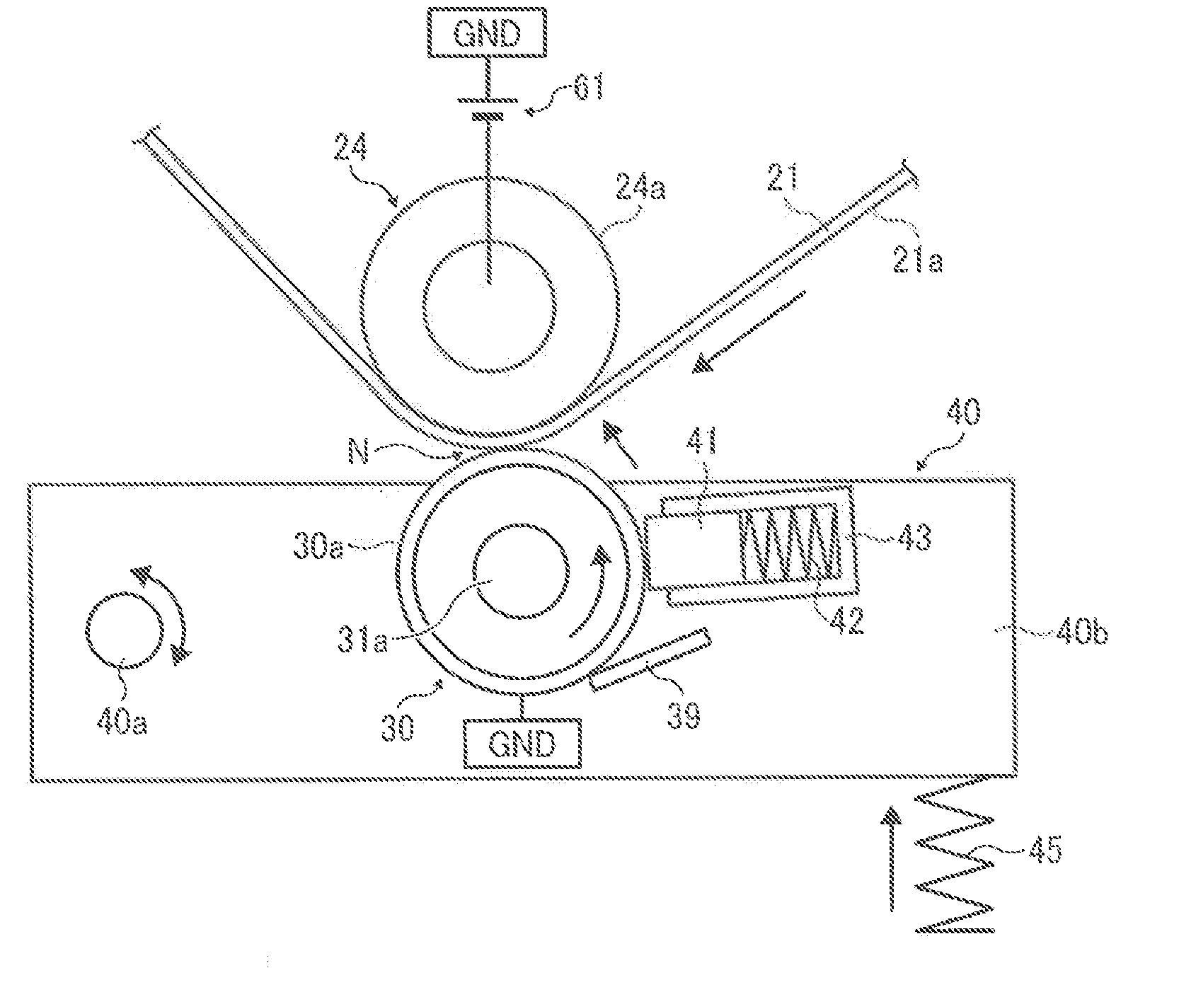
[0063]As a device to resolve such a problem, a first embodiment is described with reference to FIG. 3, wherein an enlarged cross sectional view of surroundings of a secondary transfer nip N of the transfer unit 20 is described.

[0064]As shown, the secondary transfer roller 30 includes a roller section 31 extending in a widthwise direction perpendicular to that of a recording medium member conveyance, a pair of first and second shaft members 32 and 33 protruding from both ends and extending in a rotation shaft direction, and first and second idling rollers 34 and 35. The roller section 31 includes a hollow cylindrical metal core 31a, an elastic layer 31b overlying the circumference of the metal core 31a, and a surface layer 31c overlying the circumference of the elastic layer 31b.

[0065]Material of the metal core 31a includes stainless, aluminum, and the like, but is not limited thereto. The elastic layer 31b preferably has a prescribed JIS-A hardness equal to or less than about 70 de...

second embodiment

[0106]Now, a second embodiment, in particular an exemplary sequence of a recording medium, an image and a cam position is described with reference to FIG. 12.

[0107]Different from the first embodiment even with the same configuration, a separation amount is controlled in accordance with a thickness of a recording medium when an adjustment pattern is similarly formed between sheets. In this embodiment, the controller 600 controls an operation of a cam driving motor 58 and rotation of cams 50 and 51 such that cam positions changes in an order of A, B, C, and B.

[0108]An exemplary sequence of the recording medium having a basic weight of about 300 gmm2, an image, and a cam position is described. Initially, the cams 50 and 51 are located at a position A, so that the secondary transfer roller 30 and the belt surface 21a of the intermediate transfer belt 21 contact each other as shown in FIG. 11. Then, the cams 50 and 51 rotate and are located at the position B, serving as a separation posi...

third embodiment

[0119]Such a bias control is executed by a controller 600 that also controls a high voltage power source 61. Since a configuration of the apparatus and a time for applying a secondary transfer bias are the same to those in the third embodiment, description for them are omitted hereinafter, and a secondary transfer bias applied when an adjustment pattern is formed between sheets is only described.

[0120]FIG. 17 illustrates a sequence of a sheet, an image, a position of a cam, and a secondary transfer bias when two sheets of cardboard are fed in a system similar to that in the third embodiment. When image printing for the first sheet is completed, an adjustment pattern is formed corresponding to an interval between first and second sheets. Then, under a condition that the secondary transfer roller 30 contacts the secondary transfer opposed roller 24 via the intermediate transfer belt 21 and an image section current of −30 microA and −1000V of application voltage is applied, the first s...


PUM


Abstract

An image transfer system comprises an image bearer and an opposed member having a contact surface contacting a recording medium and opposed to a surface of the image bearer to form a transfer nip. A pressing device applies pressure to the transfer nip. An engaging and disengaging member engages and disengages the contact surface from the surface of the image bearer. A transfer bias device applies a transfer bias transferring an image formed on the image bearer onto the recording medium conveyed and pinched at the transfer nip. The image is composed of an adjustment pattern formed on a portion of the image bearer corresponding to an interval between recording mediums successively conveyed through the transfer nip. The engaging and disengaging device disengages the contact surface from the surface of the image bearer to form a gap therebetween when the adjustment pattern passes therethrough.

Description

CROSS-REFERENCE TO RELATED APPLICATIONS[0001]This application claims priority pursuant to 35 USC §119 to Japanese Patent Application Nos. 2010-133058 and 2010-194913 filed on Jun. 10 and Aug. 31 both 2010, respectively, the entire contents of which are hereby incorporated by reference herein.BACKGROUND OF THE INVENTION[0002]1. Field of the Invention[0003]The present invention relates to a transfer device and an image forming apparatus having the transfer device that transfers an image onto a recording medium at a transfer nip formed between an image bearer and a transfer member contacting the image bearer.[0004]2. Description of the Background Art[0005]In an image forming apparatus which employs an engaging and disengaging mechanism capable of engaging and disengaging an opposed member from an image bearer to create a transfer nip therebetween under a prescribed bias applied from a biasing device, a linear density unevenness called an impact jitter is sometimes induced when a cardbo...

Claims


Application Information

Patent Timeline
Patent Type & Authority Applications(United States)
IPC IPC(8): G03G15/14
CPCG03G15/1675G03G2215/00059G03G15/0136G03G2215/0193G03G15/0131G03G2215/0129
Inventor SHIMIZU, YASUNOBU
Owner RICOH KK
Why Eureka
Try Eureka