Electrical contact having multiple cantilevered beams

a technology of cantilevered beams and electrical contacts, which is applied in the direction of electrical connections, coupling device connections, electrical apparatus, etc., can solve the problems of reducing the contact surface, and reducing the current carrying capacity of male pin type electrical connectors, so as to achieve the effect of small insertion for

Active Publication Date: 2014-09-02
BELLWETHER ELECTRONIC CORP
View PDF6 Cites 49 Cited by
  • Summary
  • Abstract
  • Description
  • Claims
  • Application Information

AI Technical Summary

Benefits of technology

[0017]In accordance with another embodiment, the taper angle determines a force required to insert a mating connector into the electrical contact, wherein a smaller taper angle results in a smaller insertion force.

Problems solved by technology

Most conventional miniature socket and male pin type electrical connectors have limited current carrying capability and are not suitable for high amperage.
However the necessity for the relatively large gaps reduces the contact surface and therefore lowers current carrying capacity.
Conversely, some connectors utilize large flat surfaces to carry current, but have limitations because of the surface irregularities on the mating surfaces.

Method used


Image

  • Electrical contact having multiple cantilevered beams
  • Electrical contact having multiple cantilevered beams
  • Electrical contact having multiple cantilevered beams

Examples


Embodiment Construction

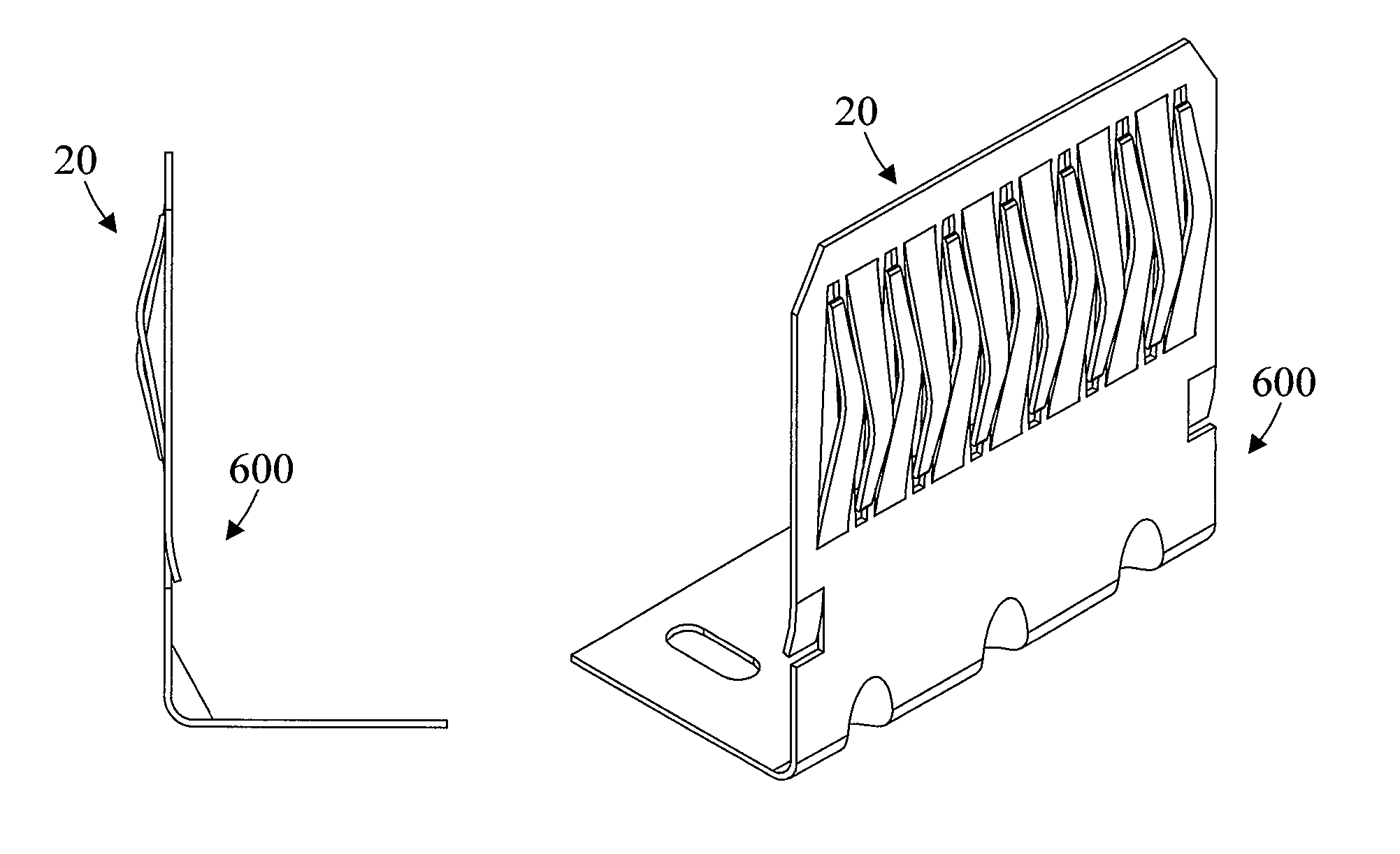
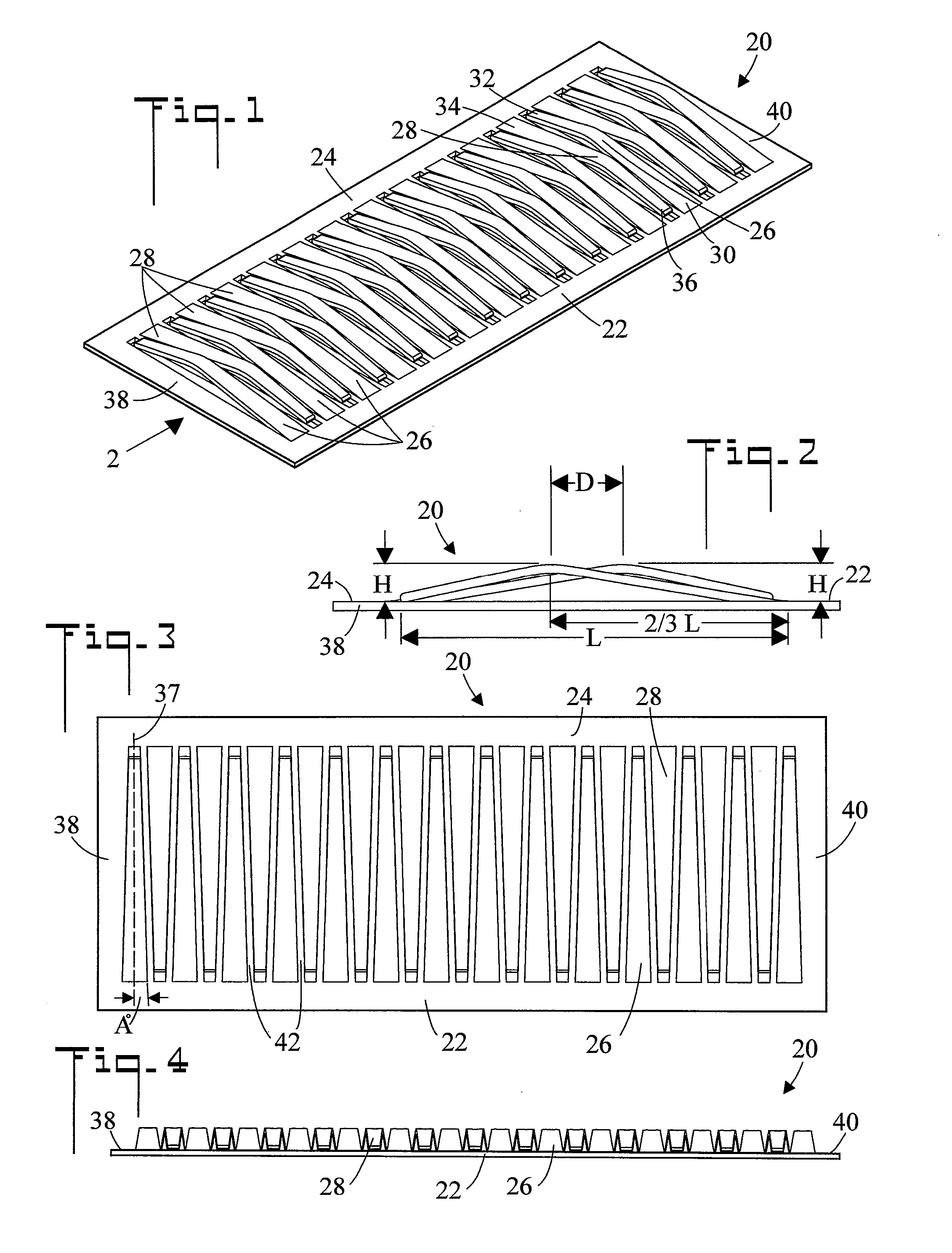
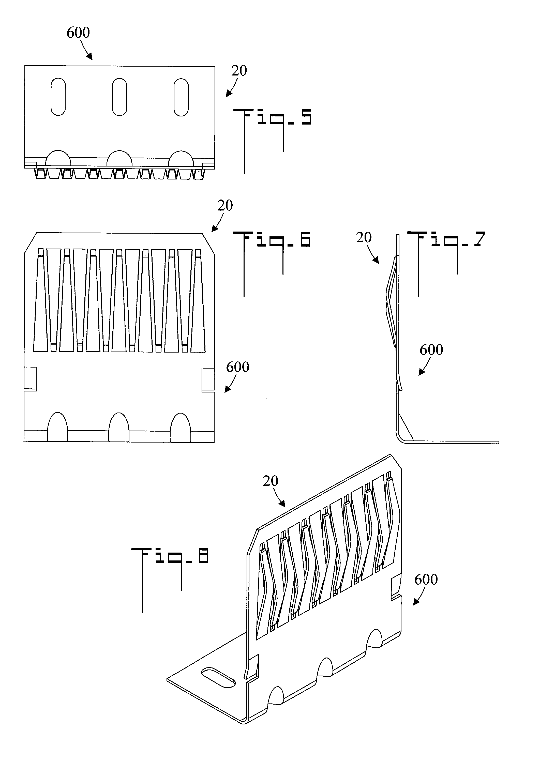
[0051]Referring initially to FIGS. 1-4, there are illustrated perspective, enlarged end, top plan, and side elevation views respectively of an electrical contact generally designated as 20. As used herein the term electrical contact means a contact which allows current to pass from one conductor to another conductor. Electrical contact 20 includes a first rail 22, and a spaced-apart second rail which is connected to and parallel with first rail 22. A plurality of spaced apart first cantilevered beams 26 are connected to first rail 22. First cantilevered beams 26 project from first rail 22 toward second rail 24. A plurality of spaced apart second cantilevered beams 28 are connected to second rail 24. Second cantilevered beams 28 project from second rail 24 toward first rail 22. First cantilevered beams 26 reside in interleaved (alternating) relationship with second cantilevered beams 28. It may be appreciated that first 22 and second rails 24 can either be elongated separate members ...


PUM


Abstract

An electrical contact includes a first set of spaced apart cantilevered beams connected to a first rail, and a second set of cantilevered beams connected to a second rail. The first set of cantilevered beams project toward the second rail, and the second set of cantilevered beams project toward the first rail, wherein the first and second sets of cantilevered beams reside in alternating relationship. Each cantilevered beam is bowed and is outwardly tapered from its connected proximal to its unconnected distal end.

Description

CROSS REFERENCE TO RELATED APPLICATION[0001]NoneTECHNICAL FIELD[0002]The present invention pertains generally to electrical connector, and more particularly to an electrical contact which has multiple cantilevered beams.BACKGROUND OF THE INVENTION[0003]Most electrical power distribution panels require connectors capable of handling high electrical current in small space. Electrical connectors which are capable of handling high amperage, and which mate to a male pin or blade, require a plurality of contact members or a large flat surface, both of which require a large area and preclude miniaturization. Most conventional miniature socket and male pin type electrical connectors have limited current carrying capability and are not suitable for high amperage.[0004]Multiple contact members can be manufactured from a strip of sheet metal with gaps between each member, and then formed into a desired shape. These gaps will allow the members to flex freely during mating and extracting of the ...

Claims


Application Information

Patent Timeline
Patent Type & Authority Patents(United States)
IPC IPC(8): H01R25/00
CPCH01R25/00H01R4/4881H01R13/187H01R13/2457H01R13/2464
Inventor THEIN, ROBERT HLATHEIN, HENRY HLA
Owner BELLWETHER ELECTRONIC CORP
Why Eureka
Try Eureka